Measuring apparatus for contact thermal conductivity of surface joint part of annular-surface contact

A measuring device, a technology of toroidal contact, applied in the direction of thermal development of materials, etc., can solve the problems of inability to measure changes in thermal characteristics, inaccurate measurement results, and long temperature stabilization time.

Inactive Publication Date: 2018-11-16
CHONGQING UNIV
View PDF7 Cites 2 Cited by
  • Summary
  • Abstract
  • Description
  • Claims
  • Application Information

AI Technical Summary

Problems solved by technology

[0004] The existing contact thermal conductance measurement devices generally have certain limitations: they can only measure plane contact thermal conductance, and cannot be widely used in the measurement of toroidal contact thermal conductance, such as the toroidal contact thermal conductance between the inner ring of a bearing and the journal. Measurement; the heat generated by the heating device is directly equated with the heat flow passing between the test pieces, ignoring the consumption of the heat flow when it is transferred on the test piece; the whole set of equipment is directly placed in the atmospheric pressure environment, and cannot measure the heat flow caused by heat convection under different environmental pressures. Changes in thermal characteristics; temperature sensors are arranged on both sides of the contact interface of the test piece, and the temperature of the measurement point is considered to be the temperature of the contact interface, but the temperature stabilization time is long, the measurement is time-consuming, and there is a certain distance from the contact interface, resulting in inaccurate measurement results

Method used


Image

  • Measuring apparatus for contact thermal conductivity of surface joint part of annular-surface contact
  • Measuring apparatus for contact thermal conductivity of surface joint part of annular-surface contact

Examples


Embodiment Construction

[0022] Embodiments of the present invention are described below through specific examples, and those skilled in the art can easily understand other advantages and effects of the present invention from the content disclosed in this specification. The present invention can also be implemented or applied through other different specific implementation modes, and various modifications or changes can be made to the details in this specification based on different viewpoints and applications without departing from the spirit of the present invention.

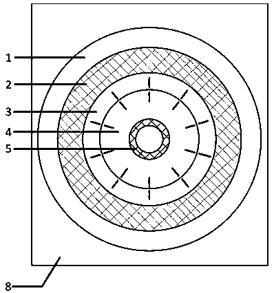
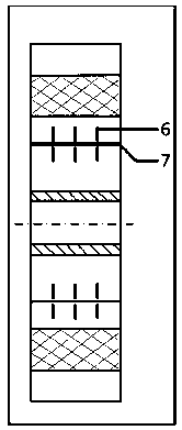
[0023] see figure 1 with figure 2 , the present embodiment of the ring-shaped contact surface junction contact thermal conductivity measurement device, including the inner and outer facing annular cooling plate and annular electric heater, temperature sensor and heat flow meter. The space between the cooling tube and the electric heater is used to load the test piece. There are two pieces to be tested, and the contact part between ...


PUM


Abstract

The invention discloses a measuring apparatus for contact thermal conductivity of a surface joint part of annular-surface contact. The measuring apparatus includes, in an inner-outer relative arrangement, an annular cooling plate, an annular electric heater, a temperature sensor, and a heat-flow meter. Two to-be-tested pieces are loaded between a cooling tube and the electric heater. The temperature sensor is used for measuring the temperature of the joint surface between the contacted to-be-tested pieces. The heat-flow meter is used for measuring the heat flow density between the two to-be-tested pieces. The measuring apparatus can accurately measure the contact thermal conductivity of the annular surface joint parts.

Description

technical field [0001] The invention relates to the technical field of contact thermal conductivity measurement, in particular to a contact thermal conductivity measurement device for a toroidal junction. Background technique [0002] When heat passes through a solid joint, a sudden drop in temperature will occur on both sides of the contact interface, that is, the existence of the contact interface hinders the smooth transfer of heat from one object to another, and the contact thermal resistance of the joint is defined to characterize this obstacle In contrast, the physical quantity that characterizes the transfer ability of heat between two solid surfaces is defined as thermal conductivity. [0003] The roughness of the contact surface causes the thermal conductivity of the contact surface to be much smaller than that of the substrate. Contact heat conduction is an important boundary condition for finite element analysis, transient thermal analysis of machine tools, and a...

Claims


Application Information

Patent Timeline
Patent Type & Authority Applications(China)
IPC IPC(8): G01N25/20
CPCG01N25/20
Inventor 马驰王时龙肖雨亮刘佳兰
Owner CHONGQING UNIV
Why Eureka
Try Eureka