
a light emitting diode

A technology of light-emitting diodes and metal electrodes, applied in nano-optics, nano-technology for materials and surface science, semiconductor devices, etc., can solve problems such as stability, response speed decline, and limit the development of RCLEDs, and achieve significant performance improvements. Enhance the external quantum efficiency of the device and improve the effect of the external quantum efficiency of the device

Active Publication Date: 2019-11-01
NANJING UNIV OF POSTS & TELECOMM
View PDF5 Cites 0 Cited by
  • Summary
  • Abstract
  • Description
  • Claims
  • Application Information

AI Technical Summary

Problems solved by technology

The reflectivity of the mirror is positively correlated with the logarithm of DBR. As the logarithm increases, its series resistance and parasitic capacitance will increase, and its stability and response speed will also decrease, which limits the development of RCLED.

Method used


Image

  • a light emitting diode
  • a light emitting diode
  • a light emitting diode

Examples


Embodiment 1

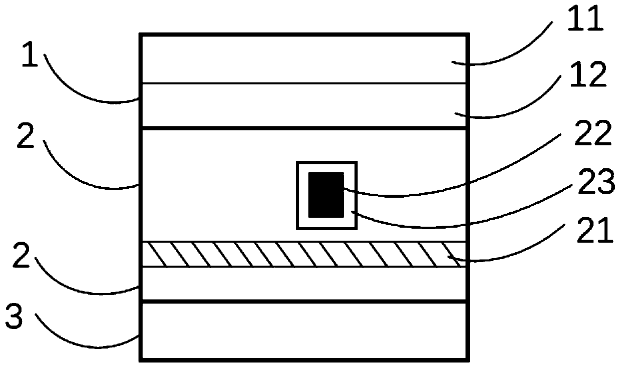
[0035] In this embodiment, the material of the transparent medium layer 11 in the single-period mirror group 1 used is SiO 2 , the refractive index of the transparent medium layer 11 is 1.4, and the thickness is 78nm.

[0036] In this embodiment, the material of the metal nano-thin layer 12 in the single-period mirror group 1 is silver, and the thickness of the metal nano-thin layer 12 is 25 nm.

[0037] In this embodiment, the thickness of the active region 2 used is 480 nm, and the refractive index of the active region 2 is 2.3.

[0038] In this embodiment, the metal electrode 3 is made of aluminum with a thickness of 200 nm.

[0039] In this embodiment, the material of the metal nanoparticles 22 used is silver, the shape of which is cubic, and the side length of the cube is 34 nm. The distance between the upper surface of the nanocube and the lower surface of the metal nano-thin layer 12 of the single-period mirror group 1 is 72 nm. The distance between the lower surface...


PUM

PropertyMeasurementUnit
thicknessaaaaaaaaaa
thicknessaaaaaaaaaa
thicknessaaaaaaaaaa

Abstract

The invention discloses a light-emitting diode. A single-period reflector group, an active region, and a metal electrode are sequentially stacked from top to bottom. The single-period reflector group includes a transparent medium thin layer and a metal nano-thin layer. The active area includes a quantum well and metal nanoparticles with a wrapping layer located above the quantum wells, and the metal nanoparticles with a wrapping layer include metal nanoparticles and a wrapping layer. In the present invention, by optimizing the thickness of the active region and the distance between the metal nanoparticles and the single-period reflector structure, the optimization and improvement of the luminous efficiency of a specific waveband can be realized.

Description

technical field [0001] The invention relates to the field of semiconductors, in particular to a light emitting diode. Background technique [0002] Light-emitting diode (LED), as the "fourth generation light source", is known as a major advancement in human lighting technology because it can reduce heat loss and save energy consumption. As well as powerful energy-saving potential and unlimited application fields, it is generally considered to be the next technology to guide the human lighting revolution after fire, incandescent lamps, and fluorescent lamps. But at present, the threshold for its real market application is still its price level and luminous efficiency. The main reason for the threshold is that the huge difference in refractive index between the material that makes up the LED and the air causes light to be totally reflected inside the LED and cannot be emitted from the device, resulting in a very low overall efficiency. In the nearly 100-year development hist...

Claims


Application Information

Patent Timeline
Patent Type & Authority Patents(China)
IPC IPC(8): H01L33/46B82Y20/00B82Y30/00
CPCB82Y20/00B82Y30/00H01L33/465
Inventor 贾博仑邓玲玲陶宇王祉又张本林陆亚琼
Owner NANJING UNIV OF POSTS & TELECOMM
Learn More