
Transmission line maintenance device

A technology for maintenance devices and transmission lines, applied in the direction of overhead lines/cable equipment, etc., which can solve the problems of no reliable backup protection for outgoing operators, long time-consuming deployment and removal, and increased workload of staff, etc., to meet manpower requirements Low, reduce the time of control work, improve the effect of clamping force

Inactive Publication Date: 2018-11-16
STATE GRID SHANDONG ELECTRIC POWER CO TAOXIAN POWER SUPPLY CO
View PDF4 Cites 6 Cited by
  • Summary
  • Abstract
  • Description
  • Claims
  • Application Information

AI Technical Summary

Problems solved by technology

Compared with the flying car, this method sometimes requires more operators, and the operators do not have reliable backup protection during the process of exiting the line, which has high potential safety hazards.
[0005] In the process of realizing the present invention, the inventor found that there are at least the following problems in the prior art: high manpower requirements, requiring multiple people to operate; relying on pulling ropes to provide forward power, and it takes a long time to lay and dismantle the ropes , affecting work efficiency, and the pulling of the rope consumes physical strength and increases the workload of the staff

Method used


Image

  • Transmission line maintenance device
  • Transmission line maintenance device
  • Transmission line maintenance device

Examples


Embodiment Construction

[0033] In order to clearly illustrate the technical features of the present solution, the present invention will be described in detail below through specific implementation methods and in conjunction with the accompanying drawings. The following disclosure provides many different embodiments or examples for implementing different structures of the present invention. To simplify the disclosure of the present invention, components and arrangements of specific examples are described below. Furthermore, the present invention may repeat reference numerals and / or letters in different instances. This repetition is for the purpose of simplicity and clarity and does not in itself indicate a relationship between the various embodiments and / or arrangements discussed. It should be noted that components illustrated in the figures are not necessarily drawn to scale. Descriptions of well-known components and processing techniques and processes are omitted herein to avoid unnecessarily lim...


PUM


Abstract

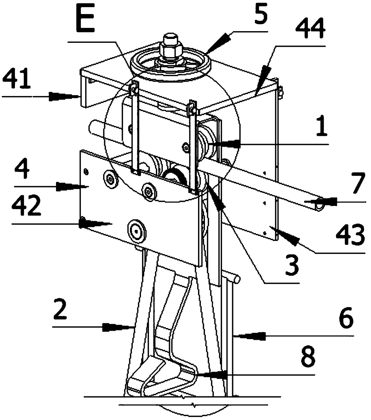
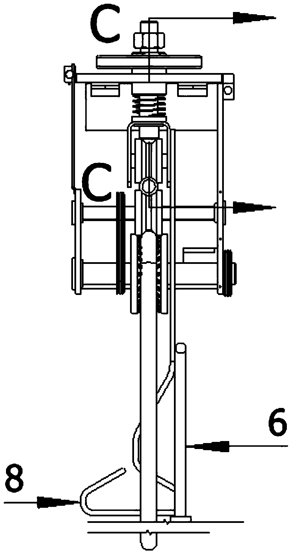
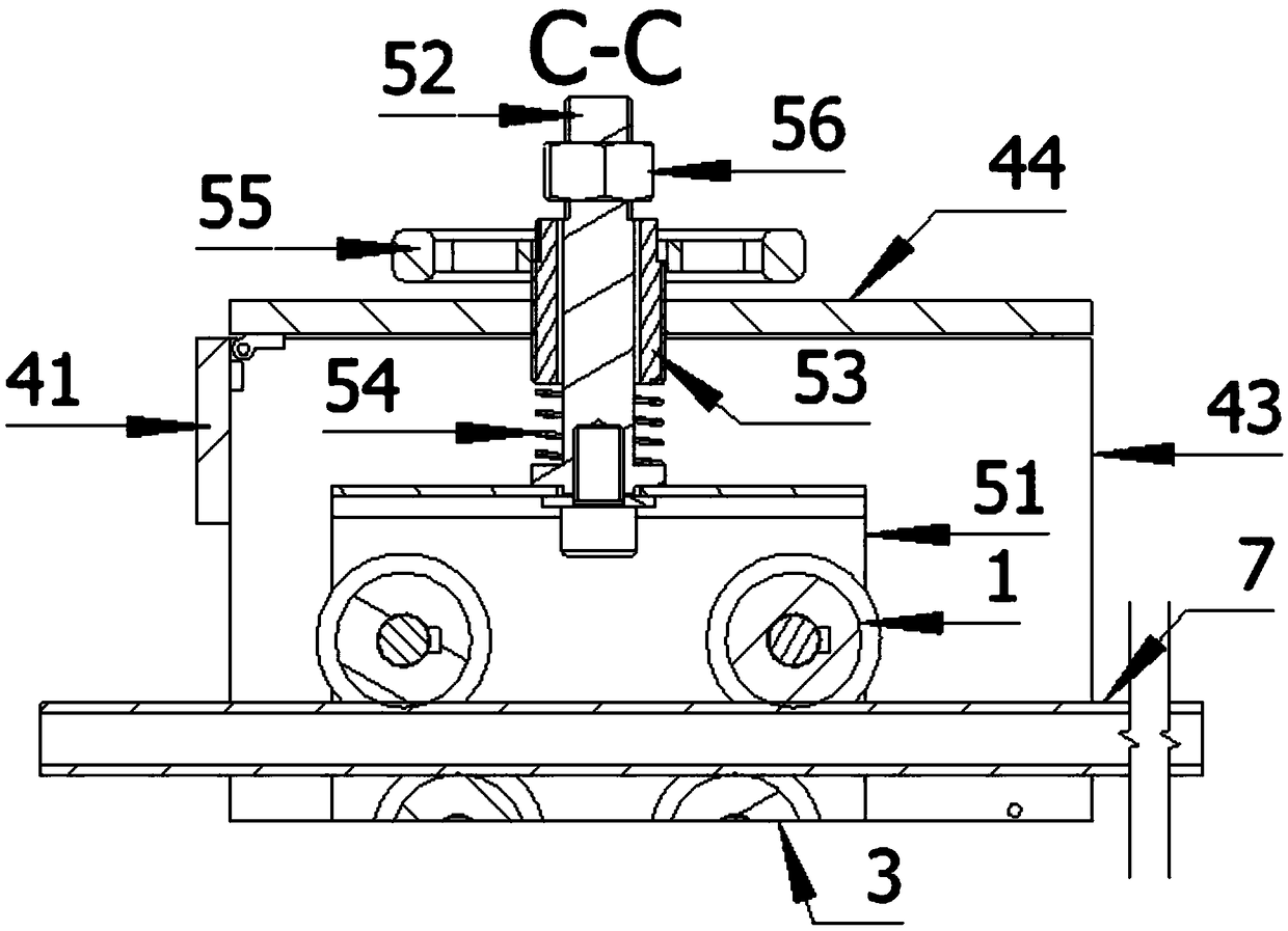
The invention discloses a transmission line maintenance device comprising a hanging wire pulley, a power mechanism, a lower clamping wheel, a housing, and a soft ladder. The hanging wire pulley and the lower clamping wheel are arranged above and below a power transmission cable. The housing consists of a back plate, a left side plate, a right side plate, and the top plate; the back plate is arranged at the top of the right side plate and is connected vertically with the right side plate; the left side plate lower than the right side plate is parallel to the right side plate and is flush with the bottom surface of the right side plate; and one end of the top plate is connected to the back plate by a hinge. Connectors corresponding to the left side plate and the right side plate are arrangedat the two sides of the top plate; the hanging wire pulley is installed below the top plate; the lower clamping wheel is installed between the left side plate and the right side plate; and the powermechanism is connected to the lower clamping wheel. The top of the soft ladder is connected to the hanging wire pulley and the lower end of the soft ladder extends to the ground. The power mechanism drives the lower clamping wheel to realize walking of the maintenance device. No complicated rope setting is needed; the maintenance device can be operated conveniently by one person; the time and manpower are saved; and the work efficiency is improved.

Description

technical field [0001] The invention relates to the technical field of power transmission line maintenance equipment, in particular to a power transmission line maintenance device. Background technique [0002] The wires and ground wires of overhead transmission lines are bare wires and are located outdoors, which are vulnerable to various external forces, such as: wind, lightning strikes, ice coating, kites, wild bird activities, etc. defect. To deal with the above defects, it is necessary for wage personnel to arrive at the wires and grounds in operation to carry out operations. The prior art usually adopts two methods of outlet. [0003] 1. Speeding out of the line: first cut off the power of the line. At least 6 operators are required to arrive at the operation site, including 2 operators on the tower and 4 on the ground. The operators on the tower take the transfer rope to the tower, and hang the transfer rope on the appropriate position of the iron tower; The infi...

Claims


Application Information

Patent Timeline
IPC IPC(8): H02G1/02
Inventor 徐龙忠袁廷辉张强刘峰赵信广郭海建刘涛赵晨旭姚景堂李超
Owner STATE GRID SHANDONG ELECTRIC POWER CO TAOXIAN POWER SUPPLY CO
Learn More