Combined converter and control method thereof
A control method and converter technology, applied in AC network circuits, wind power generation, electrical components, etc., can solve the problems of limited mechanical life and electrical life of frame circuit breakers
- Summary
- Abstract
- Description
- Claims
- Application Information
AI Technical Summary
Problems solved by technology
Method used
Image
Examples
Embodiment Construction
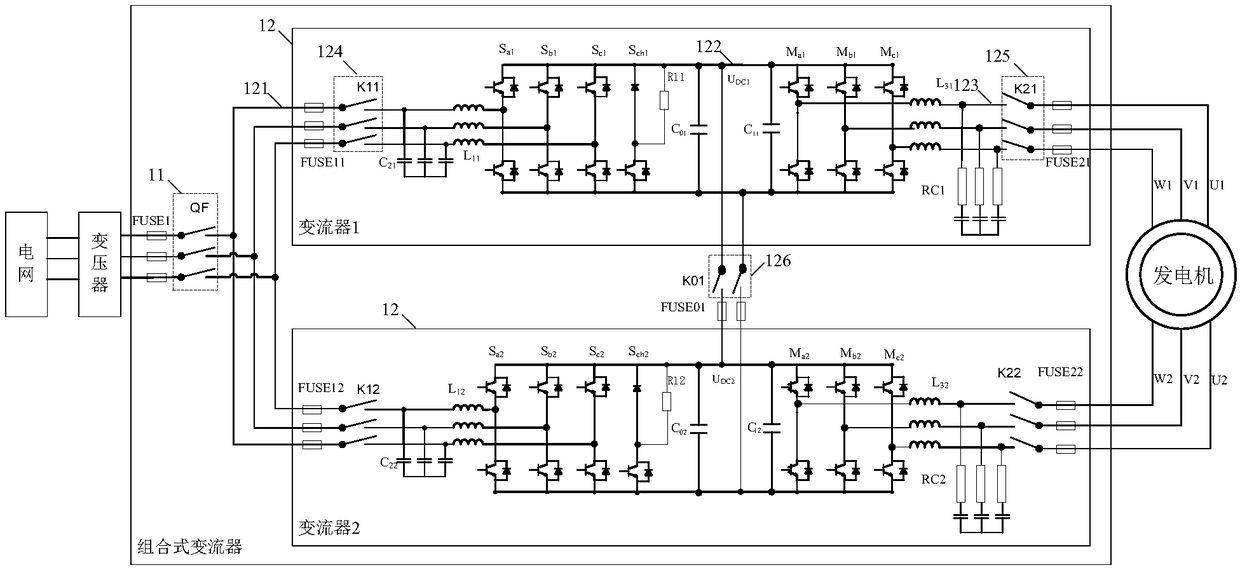
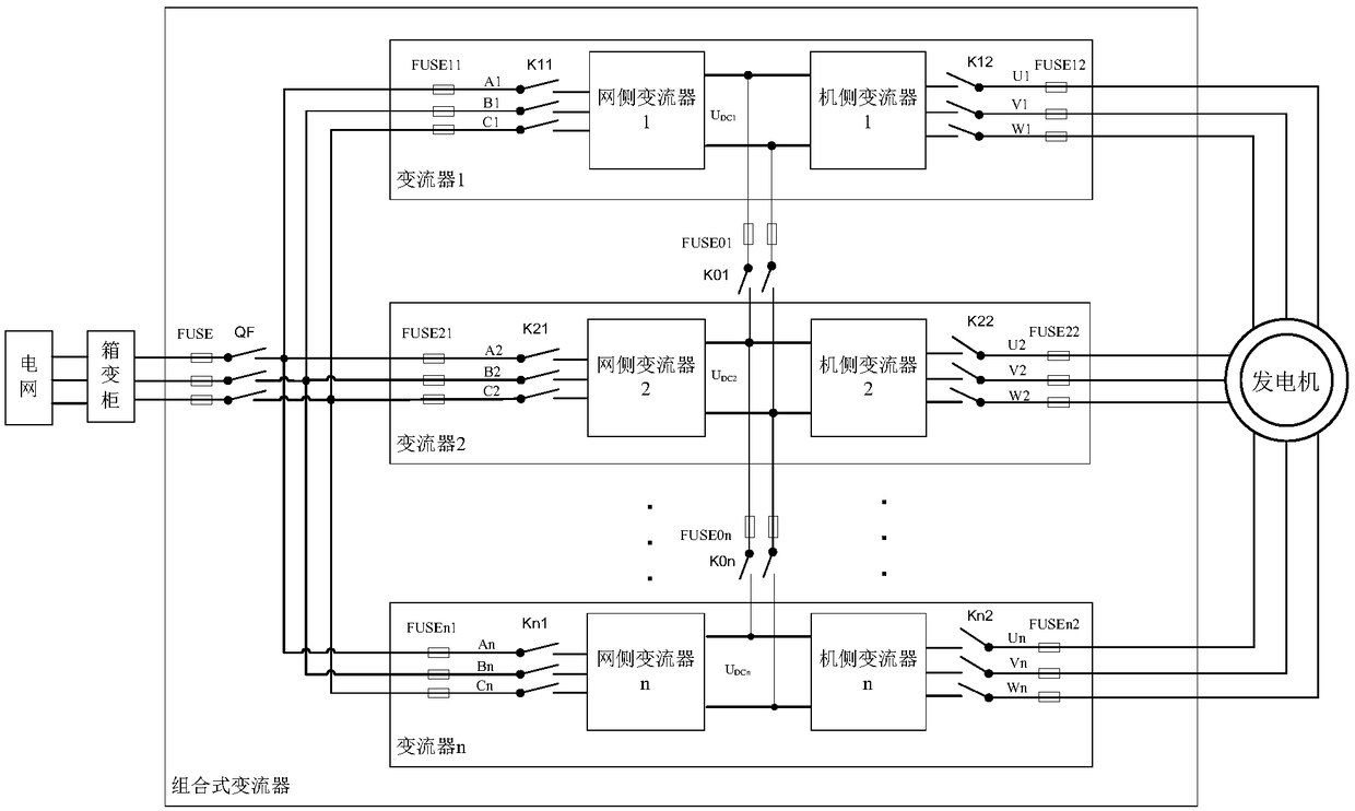
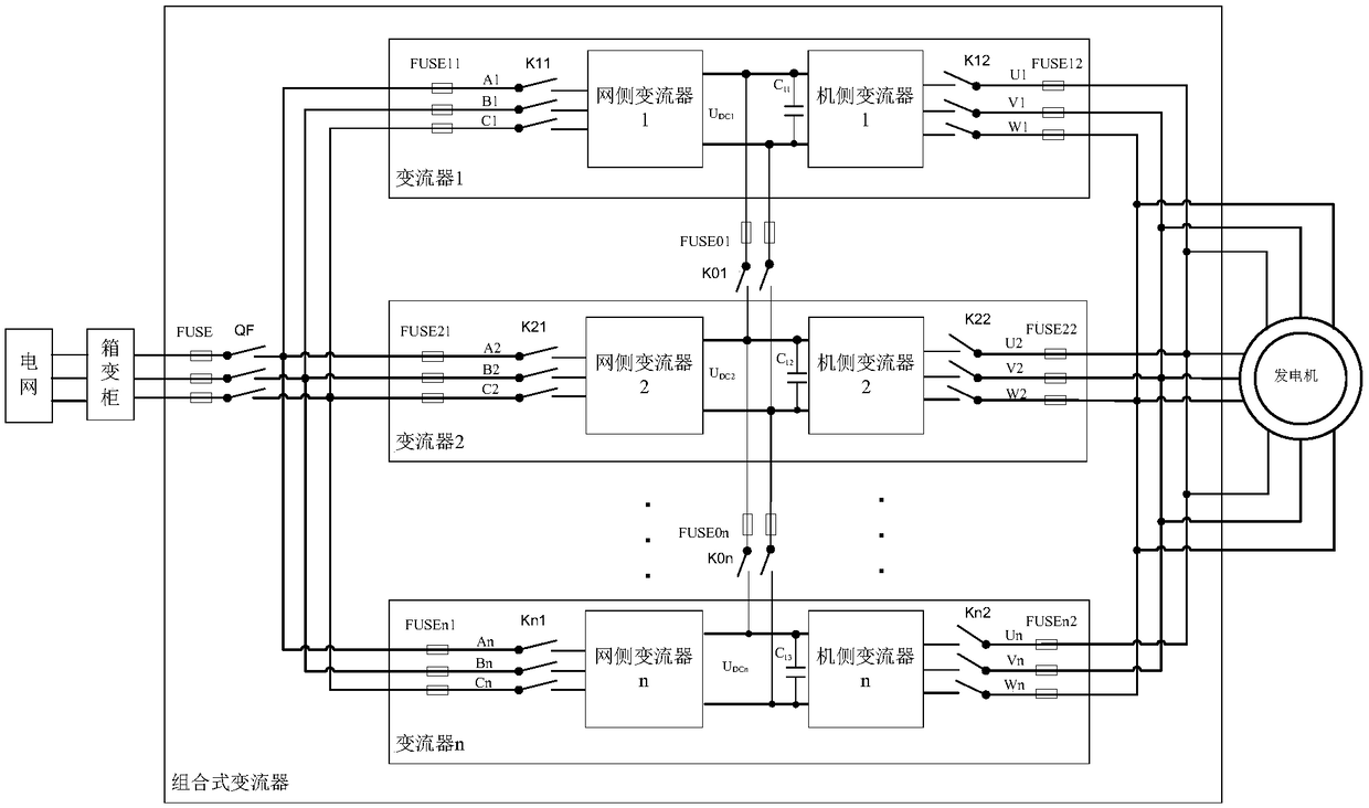
[0055] see figure 1 , figure 1 A schematic structural diagram of a combined converter provided by an embodiment of the present invention, the combined converter includes a frame circuit breaker 11 and at least two converters 12 . Wherein, each converter 12 includes an AC grid side 121 , a DC side 122 , an AC motor side 123 , a first contactor 124 and a second contactor 125 .
[0056] Specifically, the connection relationship of each device in the combined converter is:
[0057] The grid-side AC output terminal 121 of each converter 12 is connected to one end of the frame circuit breaker 11 through the first contactor 124, and the other end of the frame circuit breaker 11 is connected to the grid;
[0058]The AC motor side 123 of each converter 12 is electrically connected to the generator 13 through the second contactor 125;
[0059] The DC sides 122 of the plurality of converters 12 are all connected in parallel through the third contactor 126 .
[0060] It can be seen fr...
PUM
 Abstract
Description
Claims
Application Information
 - R&D
- Intellectual Property
- Life Sciences
- Materials
- Tech Scout
- Unparalleled Data Quality
- Higher Quality Content
- 60% Fewer Hallucinations
Browse by: Latest US Patents, China's latest patents, Technical Efficacy Thesaurus, Application Domain, Technology Topic, Popular Technical Reports.
© 2025 PatSnap. All rights reserved.Legal|Privacy policy|Modern Slavery Act Transparency Statement|Sitemap|About US| Contact US: help@patsnap.com


