Captive directional feeding structure for lambs

A technology for sheep pens and feeding troughs, applied in animal feeding devices, applications, animal husbandry, etc., can solve the problems of limited nutritional value and single feed for young sheep, achieve reasonable design and layout, prevent partial eclipse for young sheep, and simple and convenient operation Effect

Active Publication Date: 2018-11-20
广西澳茉农业科技有限公司
View PDF9 Cites 0 Cited by
  • Summary
  • Abstract
  • Description
  • Claims
  • Application Information

AI Technical Summary

Problems solved by technology

[0005] The purpose of the present invention is to solve the disadvantages in the prior art that the supplementary feed is single in the process of raising young sheep in captivity, so that the nutritional value of young sheep is limited, and a kind of directional feeding structure for young sheep in captivity is proposed

Method used


Image

  • Captive directional feeding structure for lambs
  • Captive directional feeding structure for lambs
  • Captive directional feeding structure for lambs

Examples


Embodiment 1

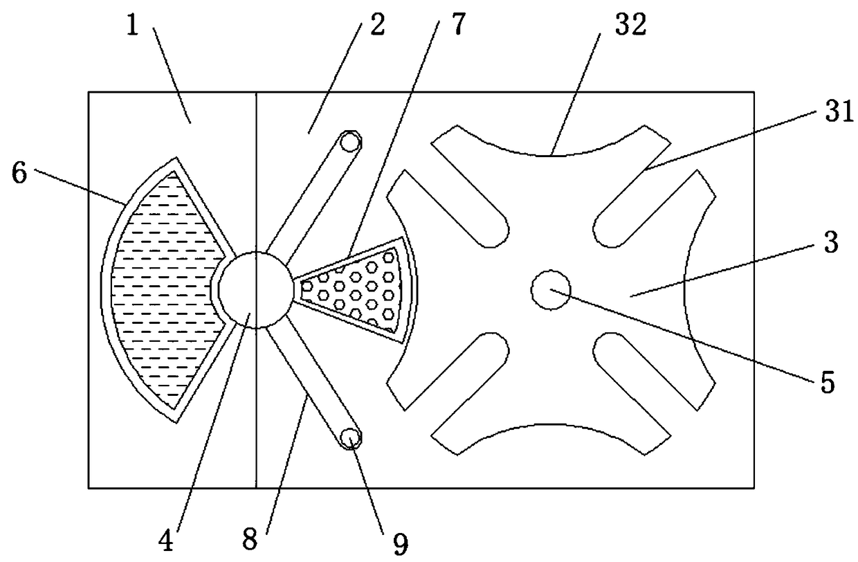
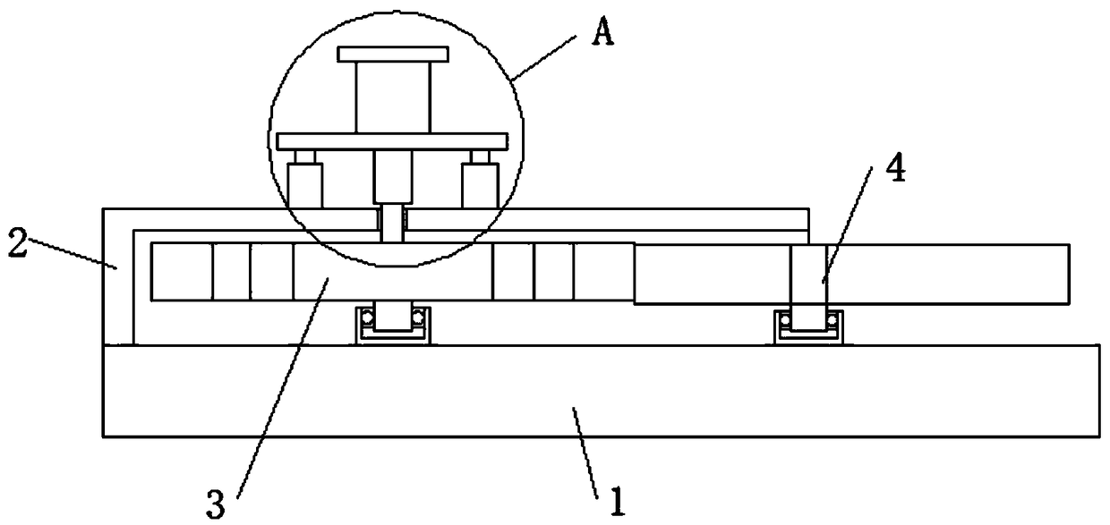
[0026] Embodiment 1, with reference to Figure 1-4 , a directional feeding structure for young sheep in captivity, comprising a base 1, a closed frame 2 is installed on the top side of the base 1, and an active plate 3 and a driven rod 4 arranged side by side are mounted on the inner rotation of the closed frame 2, wherein the active plate The periphery of 3 is provided with a plurality of power square grooves 31 and arc-shaped chutes 32, and the power square grooves 31 and arc-shaped chutes 32 are arranged in a staggered manner, and the outer wall of the driven rod 4 is welded with rows along the diameter direction of the driven rod 4. The liquid feeding trough 6, the solid feeding trough 7 and the driving long rod 8 of the cloth, the end of the driving long rod 8 away from the driven rod 4 is welded with a guide block 9, and the guide block 9 matches the power square groove 31, and the liquid feeding trough 6 All match with arc-shaped chute 32 with solid feeding groove 7, an...

Embodiment 2

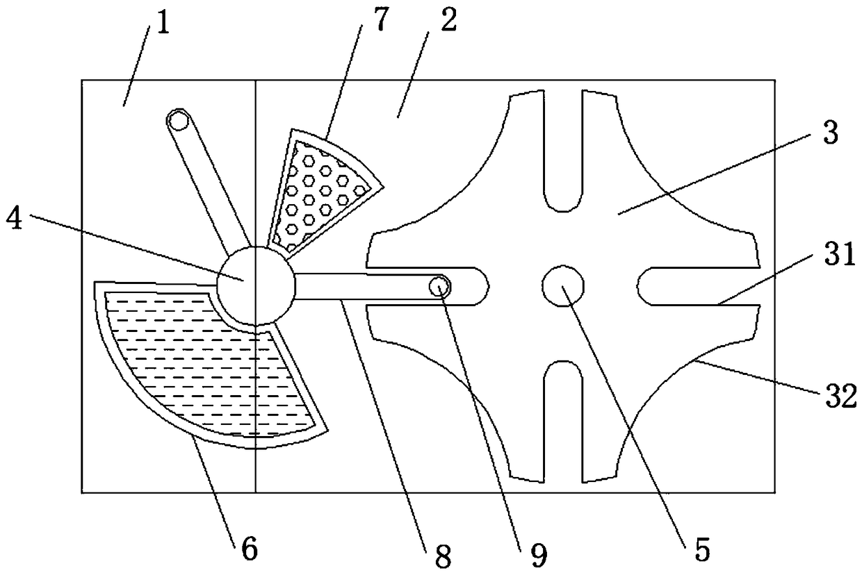
[0032] Embodiment 2, with reference to Figure 1-6, a directional feeding structure for young sheep in captivity, comprising a base 1, a closed frame 2 is installed on the top side of the base 1, and an active plate 3 and a driven rod 4 arranged side by side are mounted on the inner rotation of the closed frame 2, wherein the active plate The periphery of 3 is provided with a plurality of power square grooves 31 and arc-shaped chutes 32, and the power square grooves 31 and arc-shaped chutes 32 are arranged in a staggered manner, and the outer wall of the driven rod 4 is welded with rows along the diameter direction of the driven rod 4. The liquid feeding trough 6, the solid feeding trough 7 and the driving long rod 8 of the cloth, the end of the driving long rod 8 away from the driven rod 4 is welded with a guide block 9, and the guide block 9 matches the power square groove 31, and the liquid feeding trough 6 All match with arc-shaped chute 32 with solid feeding groove 7, and...


PUM


Abstract

The invention discloses a captive directional feeding structure for lambs. The captive directional feeding structure comprises a base, wherein a closed framework is arranged on one side of the top ofthe base; the closed framework is internally and rotationally provided with a driving plate and a driven rod which are arranged in parallel; a plurality of power square grooves and arc-shaped slidingchutes are formed in the circumferential side of the driving plate; in addition, the power square grooves are staggered with the arc-shaped sliding chutes; a liquid feeding trough, a solid feeding trough and driving long poles which are distributed along the diameter direction are welded to the outer wall of the driven rod; guide blocks are welded at the end, away from the driven rod, of the driving long poles and are matched with the power square grooves; the liquid feeding trough and the solid feeding trough are both matched with the arc-shaped sliding chutes; a rotating shaft is arranged atthe top middle position of the driving plate; a directional rotating mechanism matched with the rotating shaft is arranged at the top of the closed framework. The captive directional feeding structure disclosed by the invention has the advantages that design layout is reasonable; the lambs can be directionally and quantitatively fed and are enabled to obtain sufficient nutrition; the raising quality is improved.

Description

technical field [0001] The invention relates to the technical field of captive raising of young sheep, in particular to a directional feeding structure for captive raising of young sheep. Background technique [0002] With the development of the sheep industry, the traditional feeding methods are no longer suitable for the requirements of modern production. It is necessary to change the traditional grazing habits, develop house-feeding or semi-house-feeding sheep, and transform from the past quantity-based sheep raising to quality and benefit-based ones. To raise sheep, take the road of large-scale and ecological breeding. Raising sheep in houses is conducive to reducing production consumption, improving product quality and the benefit of raising sheep; it is conducive to returning straw to the field, providing more organic fertilizer for agriculture, increasing food production, and reducing excessive use of natural ecological resources; Improvement of the ecological enviro...

Claims


Application Information

Patent Timeline
Patent Type & Authority Applications(China)
IPC IPC(8): A01K5/01
CPCA01K5/01
Inventor 朱邵峰
Owner 广西澳茉农业科技有限公司
Why Eureka
Try Eureka