
Grinding device for wooden door plate

A technology for sheet materials and wooden doors, which is applied in the field of grinding devices for wooden door sheets, can solve problems such as large dust and affect health, and achieve the effect of preventing surface scratches

Inactive Publication Date: 2018-11-20
SICHUAN XINGZU DOOR IND CO LTD
View PDF0 Cites 0 Cited by
  • Summary
  • Abstract
  • Description
  • Claims
  • Application Information

AI Technical Summary

Problems solved by technology

[0004] The purpose of the present invention is to provide a grinding device for wooden door panels, which can solve the problem that a large amount of dust will be generated when grinding wooden doors, and the excessive inhalation of dust by workers will affect the health of the workers

Method used


Image

  • Grinding device for wooden door plate

Examples


Embodiment 1

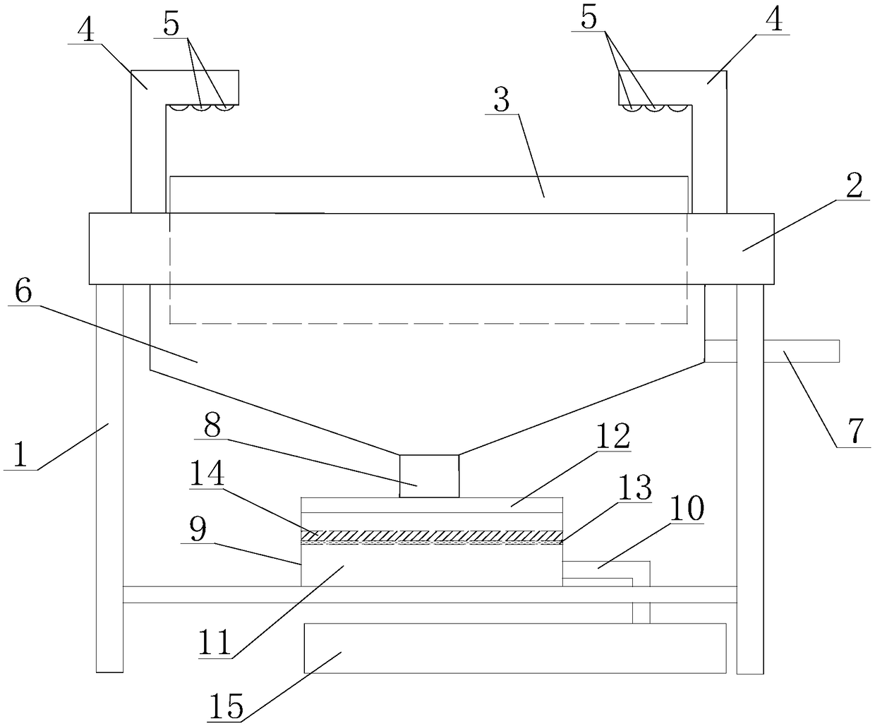
[0022] Such as figure 1 As shown, a polishing device for wood door panels in this embodiment includes a support 1 and a workbench 2. The workbench 2 is arranged on the support 1, and the upper surface of the workbench 2 is recessed to form a through hole. A plurality of grinding rollers 3 parallel to each other are arranged in the through hole. The grinding rollers 3 extend from the upper surface and the lower surface of the worktable 2, and further include a pair of L-shaped limit plates 4, the pair of L-shaped limit plates The plate 4 is arranged on the upper surface of the worktable 2 and is located on both sides of the through hole, the part of the L-shaped limiting plate 4 is located above the grinding roller 3, and the L-shaped limiting plate 4 is provided with balls 5, so The ball 5 is located above the sanding roller 3; the lower surface of the workbench 2 is provided with a dust hood 6, the upper end of the dust hood 6 communicates with the through hole, and the side w...

Embodiment 2

[0025] On the basis of Example 1, such as figure 1 As shown, the top of the box body 11 is provided with a detachable cover 12, the cover 12 is provided with an inlet, the water outlet pipe 8 is a corrugated hose, and the water outlet pipe 8 is connected to the cover 12 through the inlet. It is convenient to observe the situation inside the box by removing the lid. It is convenient to clean up the impurities deposited in the box.

Embodiment 3

[0027] On the basis of Example 1, such as figure 1 As shown, a limiting member 13 is provided on the inner wall of the box body 11, the limiting member 13 is provided above the outlet, and a filter screen 14 is provided on the limiting member 13. The filter screen is set up to limit the impurities above the outlet, avoiding excessive impurities from blocking the outlet provided on the side of the box body and causing water to be unable to drain from the box body.


PUM


Abstract

The invention discloses a grinding device for a wooden door plate. The grinding device comprises a bracket, a workbench and a pair of L-shaped limiting plates, wherein the workbench is arranged on thebracket, the upper surface of the workbench is concave inwards so as to form a through hole, a plurality of parallel grinding rollers are arranged in the through hole, the grinding rollers protrude from the upper surface and the lower surface of the workbench, the pair of L-shaped limiting plates are arranged on the upper surface of the workbench and are located on both sides of the through hole,a part of the L-shaped limiting plates are located above the grinding rollers, balls are arranged on the L-shaped limiting plates, the balls are located above the grinding rollers, a suction hood isarranged on the lower surface of the workbench, the upper end of the suction hood communicates with the through hole, a water inlet pipe is arranged on the side wall of the suction hood, a water outlet pipe is arranged on the lower end of the suction hood, a filter device is connected to the water outlet pipe, the filter device is connected with the bracket, and a drain pipe is connected to the lower end of the filter device. The amount of dust which spreads to air when a wooden door is ground is limited, so that working personnel are prevented from inhaling excessive dust so as not to influence health.

Description

Technical field [0001] The invention relates to the field of wood processing, in particular to a polishing device for wooden door panels. Background technique [0002] Wooden doors, as the name implies, are wooden doors. It can be divided into many types according to materials, crafts and uses. Especially a solid wood door, the core of the solid wood door is mostly glued with pine, fir or imported filling materials. MDF and solid wood veneer are pasted on the outside, which are made after high temperature hot pressing, and are sealed with solid wood lines. Generally, high-grade solid wood composite doors have high-quality white pine cores and solid wood veneers on the surface. Because the white pine has low density, light weight, and easier control of the moisture content, the finished door has a lighter weight and is not easy to deform or crack. In addition, the solid wood composite door also has the characteristics of heat preservation, impact resistance, flame retardancy, ...

Claims


Application Information

Patent Timeline
Patent Type & Authority Applications(China)
IPC IPC(8): B24B55/06B27G3/00
CPCB24B55/06B27G3/00
Inventor 汤劲旅
Owner SICHUAN XINGZU DOOR IND CO LTD
Learn More