Supercharge Your Innovation With Domain-Expert AI Agents!

Crankshaft, compressor and refrigeration equipment

A technology of refrigeration equipment and compressors, which is applied in the field of compressors, can solve the problems of large processing loss, low reliability, and difficult standardization of crankshaft parts, and achieve the effects of reducing processing and manufacturing costs, high reliability, and realizing standardization

Inactive Publication Date: 2018-11-20
GUANGDONG WELLING AUTO PARTS CO LTD
View PDF6 Cites 0 Cited by
  • Summary
  • Abstract
  • Description
  • Claims
  • Application Information

AI Technical Summary

Problems solved by technology

The problems of this processing method are: the machining allowance of the crankshaft is large, the processing loss is large, the material cost and processing cost are high; the crankshaft parts are difficult to standardize, and the production management is troublesome
However, this technology of fixing by welding has the risk of fatigue failure and has the defect of low reliability

Method used


Image

  • Crankshaft, compressor and refrigeration equipment
  • Crankshaft, compressor and refrigeration equipment
  • Crankshaft, compressor and refrigeration equipment

Examples


Embodiment 1

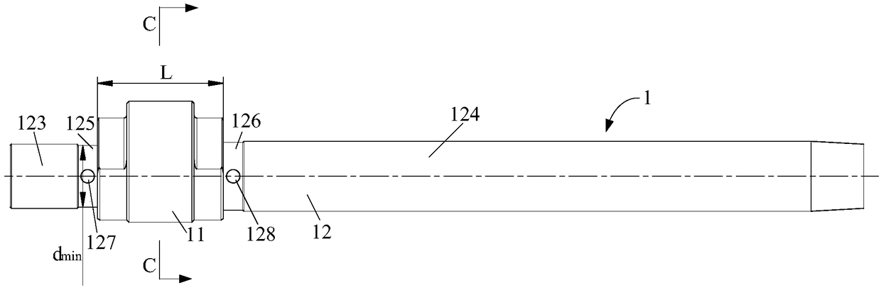
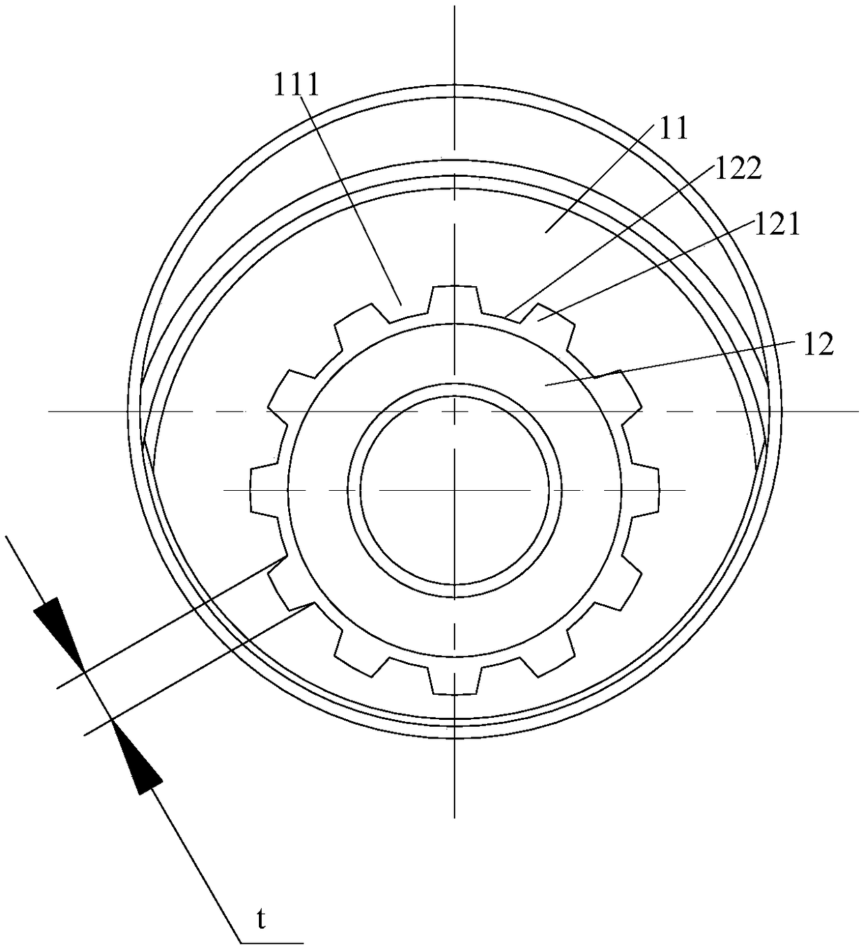
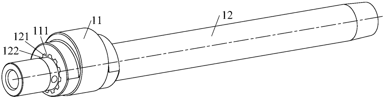
[0057] like Figure 1 to Figure 5 As shown, a crankshaft according to this embodiment includes a linear shaft 12 and an eccentric portion 11 . The eccentric part 11 is provided with a rough mounting hole 112, which is eccentrically arranged with the outer diameter of the eccentric part 11, and is provided with protrusions 111 along the axial direction, and the protrusions 111 are evenly distributed along the circumference of the mounting hole 112, and the number is n. A part of the linear shaft 12 is set in the installation hole 112, and the outer wall surface of the part where the linear shaft 12 cooperates with the eccentric part 11 is provided with a protruding structure 121, and the groove 122 and the protrusion 111 formed between the protruding structures 121 Fitted with each other to form a form-fit in the circumferential direction. A concave position is formed between two adjacent protrusions, and the protruding structure is located in the concave position.

[0058] ...

Embodiment 2

[0066] like Figure 6 As shown, a crankshaft according to Embodiment 2 is substantially the same as Embodiment 1. The difference is that the cross-sectional profile of the protrusion 111 and the protruding structure 121 in this embodiment is roughly in the shape of an involute gear tooth, that is, the cross-section of the protrusion 111 and the protruding structure 121 contains at least one circle involute.

[0067] According to the crankshaft of this embodiment, the protrusion 111 and the protrusion structure 121 can use existing gear design and processing methods, thereby reducing development and manufacturing costs.

Embodiment 3

[0069] like Figure 7 As shown, a crankshaft according to Embodiment 3 is substantially the same as Embodiment 1. The difference is that the cross-sections of the protrusion 111 and the protruding structure 121 in this embodiment include at least one arc.

[0070] According to the crankshaft of this embodiment, the protrusion and the protruding structure have a larger cross-sectional area and are easy to process.


PUM


Abstract

The invention provides a crankshaft, a compressor and refrigeration equipment. The crankshaft comprises an eccentric part and a linear shaft; a mounting hole is formed in the eccentric part and eccentrically formed; and the linear shaft penetrates through the mounting hole, a protrusion is arranged on one of the hole wall of the mounting hole and the outer wall face of the linear shaft, a groove matched with the protrusion is formed in another of the hole wall of the mounting hole and the outer wall face of the linear shaft, and the protrusion is located in the groove. According to the crankshaft, the linear shaft and the eccentric part are of a split structure, shape locking of the linear shaft and the eccentric part is formed by cooperation of the protrusion and the groove, reliability is high, the problem of low reliability caused by welding of the linear shaft and the eccentric part is avoided, standardization of the linear shaft and the eccentric part can be achieved, and the machining and manufacturing cost of the crankshaft is lowered.

Description

technical field [0001] The present invention relates to the field of compressors, more specifically, to a crankshaft, a compressor including the crankshaft, and refrigeration equipment including the compressor. Background technique [0002] The crankshaft of the existing rotary compressor has an integral structure, and the linear shaft and the eccentric part of the crankshaft are integrally formed into an integral blank, such as a cast blank or a forged blank. The blank parts are then machined to gradually obtain the finished crankshaft. The problems of this kind of processing method are: the machining allowance of the crankshaft is large, the processing loss is large, the material cost and processing cost are high; the crankshaft parts are difficult to standardize, and the production management is troublesome. [0003] In order to solve this problem, some literature discusses designing the crankshaft as a split structure, processing the linear shaft part and the eccentric ...

Claims


Application Information

Patent Timeline
IPC IPC(8): F04C29/00F04C18/10
CPCF04C29/00F04C18/10F04C2240/601
Inventor 康晓虎卢志富杨国用
Owner GUANGDONG WELLING AUTO PARTS CO LTD
Features
  • R&D
  • Intellectual Property
  • Life Sciences
  • Materials
  • Tech Scout
  • Unparalleled Data Quality
  • Higher Quality Content
  • 60% Fewer Hallucinations
Learn More