Check patentability & draft patents in minutes with Patsnap Eureka AI!

Automobile braking idler wheel

A technology for automobile braking and rollers, which is applied in the directions of brake parts, engine components, and engine lubrication. Long-term lubrication effect

Inactive Publication Date: 2018-11-20
ANHUI TIANYU AUTO PARTS MFG
View PDF6 Cites 2 Cited by
  • Summary
  • Abstract
  • Description
  • Claims
  • Application Information

AI Technical Summary

Problems solved by technology

[0002] The braking system is a device used on a car to apply a certain force to certain parts of the car from the outside, so as to perform a certain degree of forced braking on it. The usual braking system is divided into a drum brake system and a disc brake system. , in the drum brake system, the rotation of the brake camshaft will drive a certain amount of friction between the brake roller and the brake shoe, resulting in wear of some parts. When the brake roller rolls, it will contact the brake roller The bushing on the inner surface has a certain amount of friction, which causes a certain amount of wear on the bushing, but the existing bushing is generally installed inside the brake roller, so it is impossible to directly observe the wear degree of the bushing, and it is even more inconvenient to judge whether the bushing needs Replacement will cause certain difficulties to the inspection and maintenance of the staff, and for the convenience of lubrication, self-lubricating bushes are now used for lubrication, but the existing self-lubricating bushes need continuous contact with solid lubricants Only when it is lubricated, the self-lubricating time has a certain period, if the self-lubricating time is not long enough, the staff may need to add lubricant for lubrication in the future

Method used


Image

  • Automobile braking idler wheel
  • Automobile braking idler wheel
  • Automobile braking idler wheel

Examples


Embodiment Construction

[0026] The following will clearly and completely describe the technical solutions in the embodiments of the present invention with reference to the accompanying drawings in the embodiments of the present invention. Obviously, the described embodiments are only some, not all, embodiments of the present invention. Based on the embodiments of the present invention, all other embodiments obtained by persons of ordinary skill in the art without making creative efforts belong to the protection scope of the present invention.

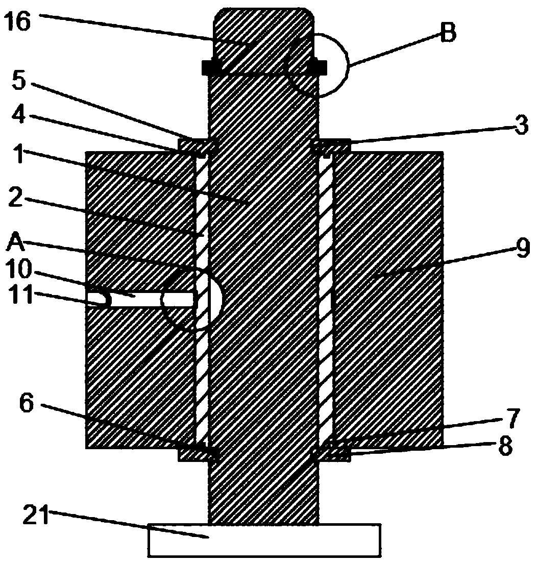
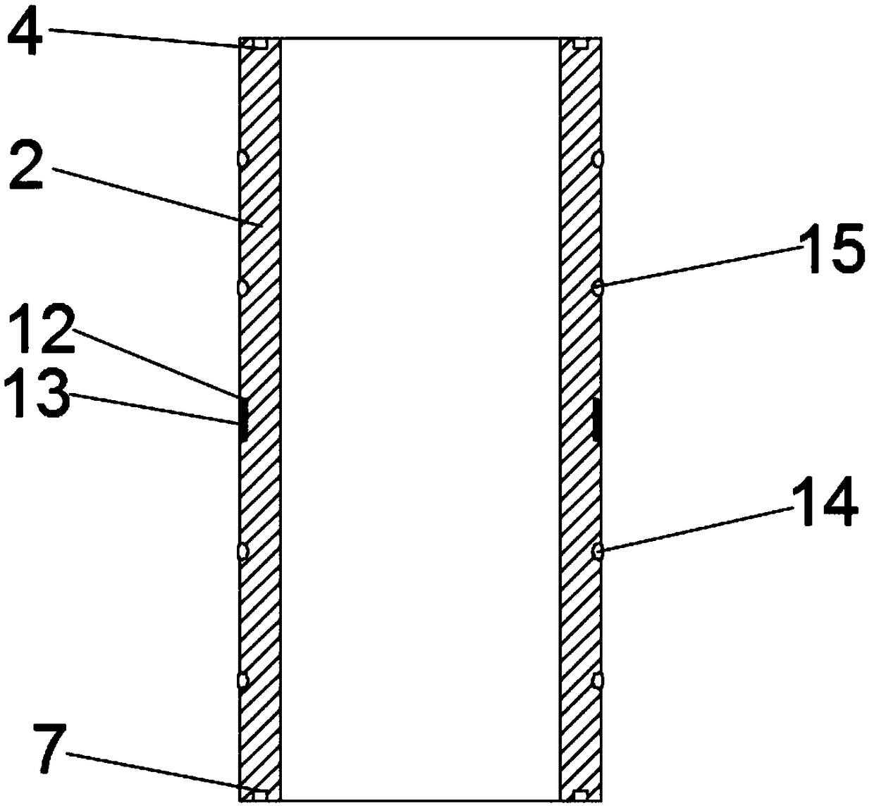
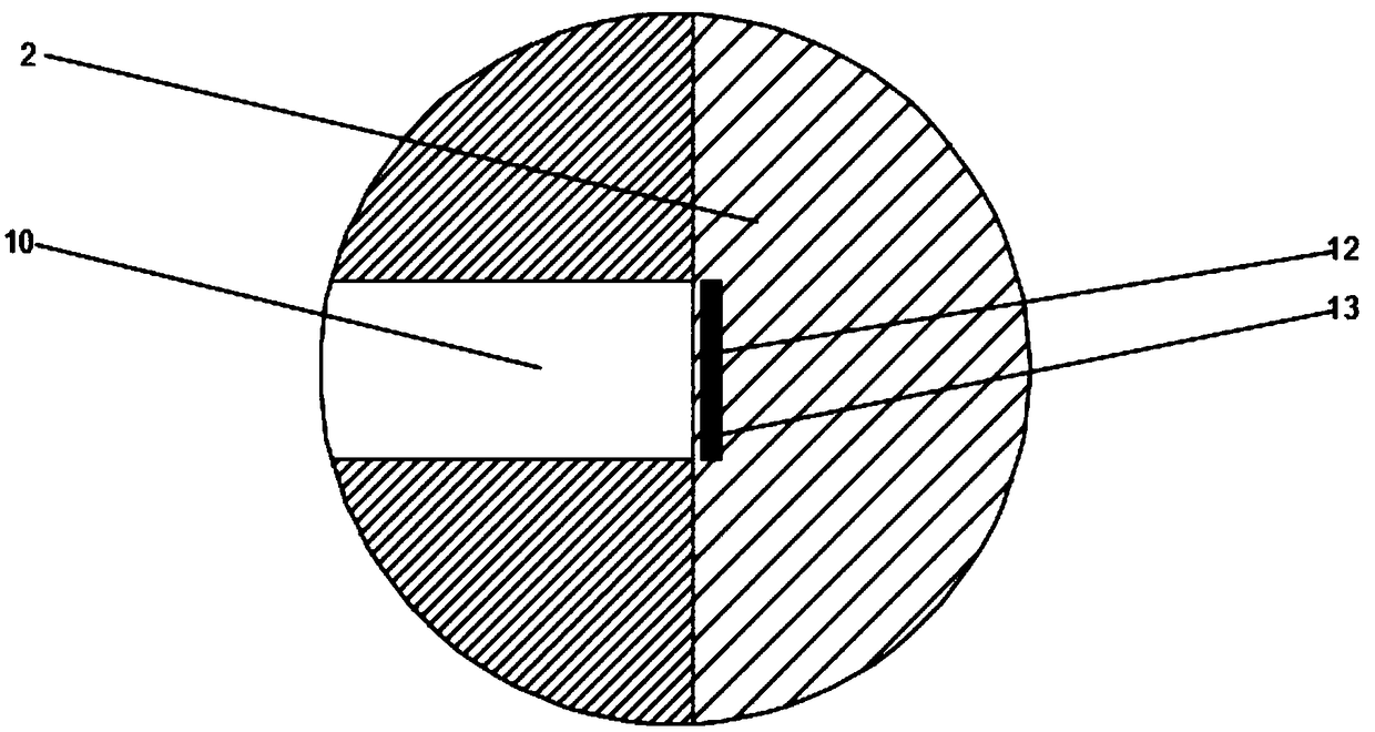
[0027] see Figure 1-5 , the present invention provides a technical solution: a car brake roller, including a roller installation shaft 1, a bushing 2 is movably connected to the middle of the outer wall of the roller installation shaft 1, and the outer surface of the roller installation shaft 1 is located at the upper side of the bushing 2 A first installation groove 3 is opened, a first seal groove 4 is opened on the top of the bushing 2, a first seal ring 5...


PUM


Abstract

The invention discloses an automobile braking idler wheel, and relates to the technical field of automobile braking. The automobile braking idler wheel comprises an idler wheel mounting shaft. The middle of the outer wall of the idler wheel mounting shaft is movably connected with a lining; a first mounting groove is formed in the position, on the upper side of the lining, of the outer surface ofthe idler wheel mounting shaft; a first sealing groove is formed in the top of the lining and connected to the inner surfaces of a first sealing sleeve ring and the first mounting groove; and a secondmounting groove is formed in the position, on the lower side of the lining, of the outer surface of the idler wheel mounting shaft. According to the automobile braking idler wheel, the purposes thatthe abrasion degree of the lining can be directly observed, and self-lubricating can be durably conducted are achieved, a worker can directly judge whether the lining needs to be replaced or not afterobserving the color directly through an observation hole, thus the lining is observed and replaced more conveniently, and the work efficiency is improved; and the automobile braking idler wheel can conduct continuous self-lubricating by stages, the lubricating time is long, manual subsequent adding of lubricating oil is not needed, and normal operation of the automobile braking idler wheel is guaranteed.

Description

technical field [0001] The invention relates to the technical field of vehicle braking, in particular to an automobile braking roller. Background technique [0002] The braking system is a device used on a car to apply a certain force to certain parts of the car from the outside, so as to perform a certain degree of forced braking on it. The usual braking system is divided into a drum brake system and a disc brake system. , in the drum brake system, the rotation of the brake camshaft will drive a certain amount of friction between the brake roller and the brake shoe, resulting in wear of some parts. When the brake roller rolls, it will contact the brake roller The bushing on the inner surface has a certain amount of friction, which causes a certain amount of wear on the bushing, but the existing bushing is generally installed inside the brake roller, so it is impossible to directly observe the wear degree of the bushing, and it is even more inconvenient to judge whether the ...

Claims


Application Information

Patent Timeline
IPC IPC(8): F16D65/02F16N1/00
CPCF16D65/02F16N1/00
Inventor 李支峰
Owner ANHUI TIANYU AUTO PARTS MFG
Features
  • R&D
  • Intellectual Property
  • Life Sciences
  • Materials
  • Tech Scout
  • Unparalleled Data Quality
  • Higher Quality Content
  • 60% Fewer Hallucinations
Learn More