
Suction-type electronic chip cooling boiling enhanced heat transfer experiment device and method

A technology for strengthening heat exchange and experimental equipment, applied in the direction of material thermal development, etc., can solve the problems of reducing the critical heat flux density of boiling heat transfer, and the rapid separation of bubbles on the chip surface cannot be well combined, so as to improve the critical heat flux density, The pipeline layout is compact and simple, and the effect of reducing the superheat on the wall

Active Publication Date: 2018-11-20
XI AN JIAOTONG UNIV
View PDF9 Cites 3 Cited by
  • Summary
  • Abstract
  • Description
  • Claims
  • Application Information

AI Technical Summary

Problems solved by technology

At present, most literatures focus on the experimental research of pool boiling, flow boiling, and jet impingement boiling. However, the above boiling methods more or less suppress the generation of bubbles while taking away the bubbles, thus reducing the boiling heat transfer. critical heat flux
At the same time, the strengthening features such as rapid detachment of bubbles on the chip surface, rapid replenishment of cold fluid and suitable surface cooling range cannot be well combined.

Method used


Image

  • Suction-type electronic chip cooling boiling enhanced heat transfer experiment device and method
  • Suction-type electronic chip cooling boiling enhanced heat transfer experiment device and method
  • Suction-type electronic chip cooling boiling enhanced heat transfer experiment device and method

Examples


Embodiment Construction

[0029] Below in conjunction with accompanying drawing, the present invention is described in further detail:

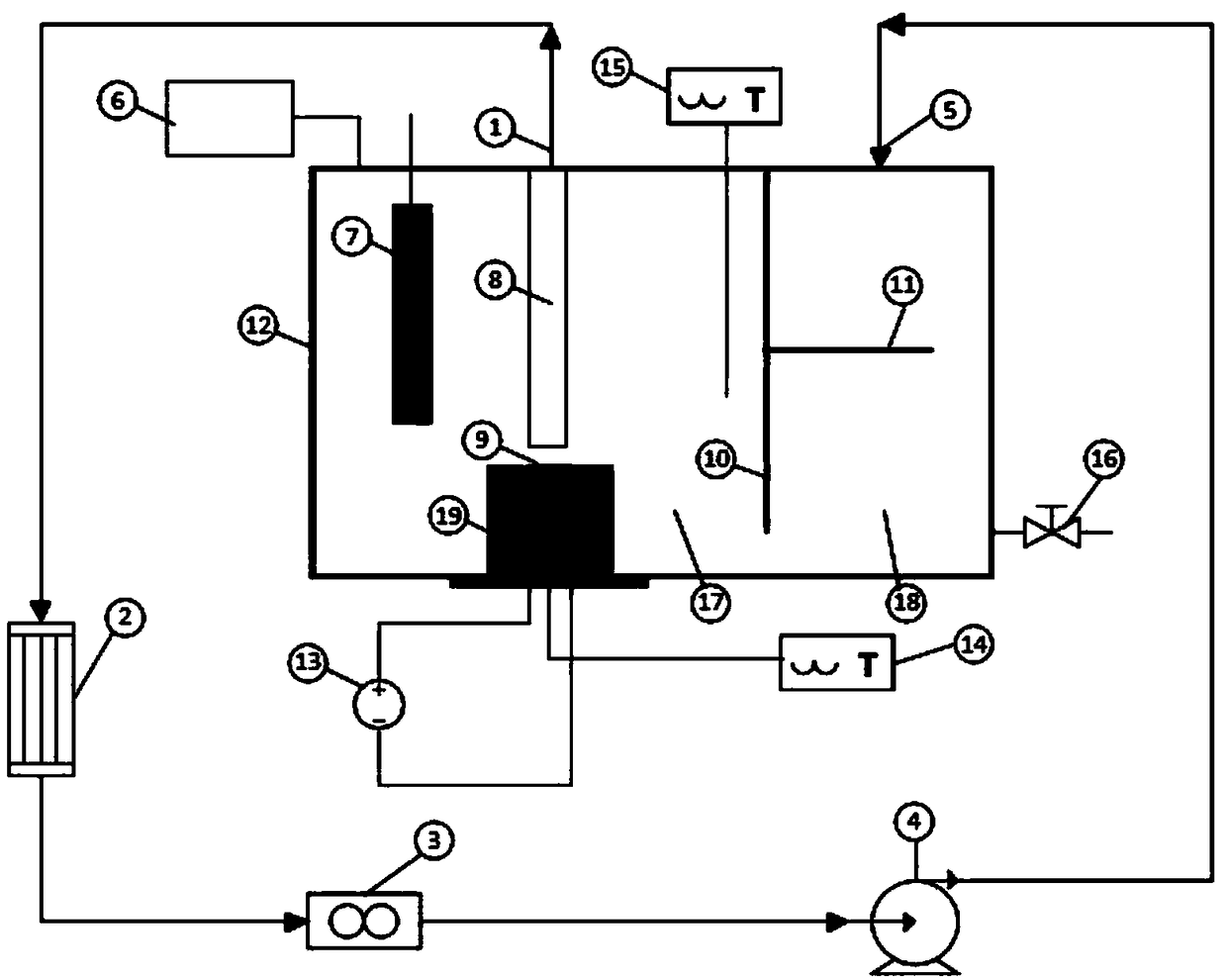
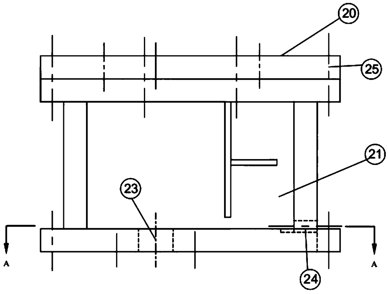
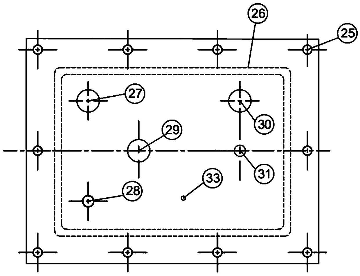
[0030] refer to figure 1 and Figure 3-1 , a pumping type electronic chip cooling enhanced boiling heat transfer experimental device, comprising a DC pump 4, a potentiometer for adjusting the speed of the DC pump, a flow meter 3, a condenser 2 and a suction experiment boiling pool 12; the suction experiment boiling The bottom of the pool 12 is embedded with a loading boss 23, the test chip 9 is fixed on the groove 34 above the loading boss 23, and the test chip 9 is pasted in the groove 34 by heat-insulating silica gel; Divided into two cavities, the two cavities are separated by a partition 10 with a bottom opening of 10 mm, one is a suction cavity 17, and a suction tube bundle 8 is arranged directly above the test chip 9 to extract the surrounding air bubbles and working medium mixture, and the other is a suction cavity 17. One is the liquid discharge chamber 18. ...


PUM


Abstract

The invention discloses a suction-type electronic chip cooling boiling enhanced heat transfer experiment device and a suction-type electronic chip cooling boiling enhanced heat transfer experiment method. The suction-type electronic chip cooling boiling enhanced heat transfer experiment device comprises a suction experiment boiling tank, wherein the suction experiment boiling tank is partitioned into a suction chamber and a liquid draining chamber through a partition board with an opening in the lower side; a carrying lug boss is mounted on a bottom plate of the suction experiment boiling tank; the upper part of the carrying lug boss stretches into the suction chamber; a test chip is arranged on the upper part of the carrying lug boss; the two ends of the test chip are connected to a direct current power supply through conductive wires; a suction tube bundle is arranged right above the test chip; the suction tube bundle is connected to a condenser through a liquid conveying pipe connected to the suction experiment boiling tank; the outlet end of the condenser is connected to a liquid returning pipe through a unidirectional flow pump; the liquid returning pipe is connected to the suction experiment boiling tank; the liquid returning pipe is communicated with the liquid draining chamber. The suction-type electronic chip cooling boiling enhanced heat transfer experiment device generates a low pressure through suction, so that bubble removal from the surface of the chip and rapid replenishment of a surrounding cold fluid are accelerated; the suction-type electronic chip coolingboiling enhanced heat transfer experiment device has the advantages of flexible operation, simple control, small floor space, convenient chip replacement and the like.

Description

technical field [0001] The invention relates to the technical field of electronic chip cooling and enhanced boiling heat transfer, in particular to a pumping type electronic chip cooling and boiling enhanced heat transfer experimental device and method. Background technique [0002] With the rapid development of microelectronics technology, the integration level and operating frequency of large-scale integrated circuits on chips continue to increase, and the feature size of electronic devices is getting smaller and smaller, so the cooling problem of chips has become more and more prominent. Traditional air cooling and other cooling technologies are difficult to take away a large amount of heat in time. Direct liquid cooling of chips using boiling phase transfer heat is an effective cooling method. The usual method is to directly immerse chips in non-conductive liquids Boiling heat exchange is carried out, but there are problems such as high boiling initial temperature, which...

Claims


Application Information

Patent Timeline
IPC IPC(8): G01N25/20
CPCG01N25/20
Inventor 张永海余昕桐刘斌魏进家
Owner XI AN JIAOTONG UNIV
Learn More