an electronic cigarette

A technology of electronic cigarettes and smoke chambers, applied in the field of electronic cigarettes, can solve the problems such as the inability to collect soot, and achieve the effect of avoiding flying of soot, avoiding pollution of the environment, and solving the effect of damaging clothes

Active Publication Date: 2021-04-06
龙其壹
View PDF6 Cites 0 Cited by
  • Summary
  • Abstract
  • Description
  • Claims
  • Application Information

AI Technical Summary

Problems solved by technology

[0004] The technical problem mainly solved by the embodiments of the present invention is to provide an electronic cigarette, which solves the technical problem that the soot cannot be collected due to the absence of a soot collection device when smoking real cigarettes on special occasions

Method used


Image

  • an electronic cigarette
  • an electronic cigarette
  • an electronic cigarette

Examples


Embodiment 1

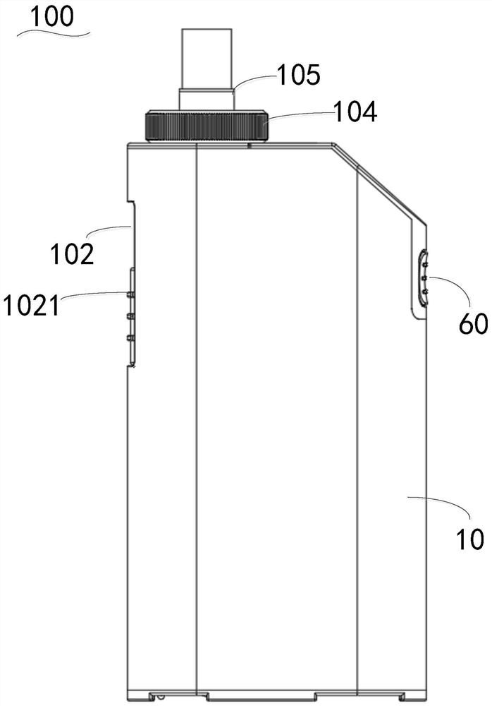
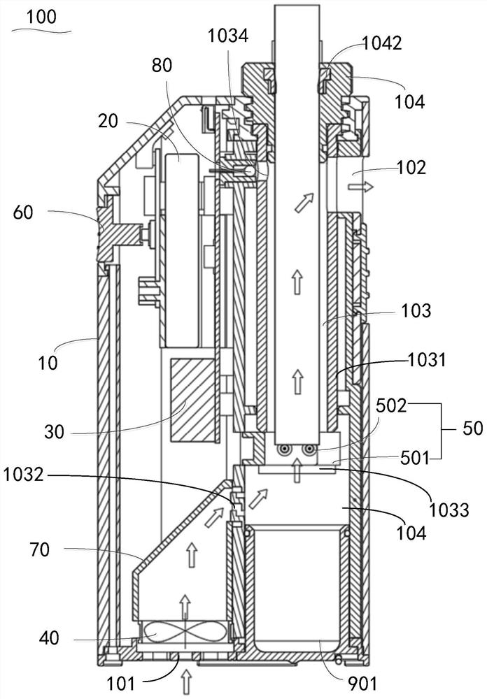
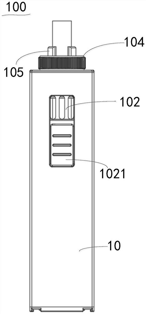
[0027] Please also refer to figure 1 , figure 2 and image 3 , the embodiment of the present invention provides an electronic cigarette 100 , including: a box body 10 , a power supply assembly 20 , a high voltage generator 30 , a controller (not shown in the figure), a fan 40 , an ignition assembly 50 and a switch assembly 60 .

[0028] Above-mentioned box body 10 comprises air inlet 101, air outlet 102, smoke chamber 103 and chamber mouth (not shown), and described chamber mouth is positioned at the top of described box body 10, and the upper end of described smoke chamber 103 and described chamber The bottom end of the smoke cavity 103 is located at the bottom of the box body 10, the air inlet 101 is arranged at the bottom of the box body 10 and away from the position of the smoke cavity 103, and the gas outlet 102 It is arranged on the side wall of the smoke cavity 103, the gas outlet 102 communicates with the smoke cavity 103, the smoke cavity 103 communicates with the ...

Embodiment 2

[0057] Please also refer to figure 2 and Figure 6 , the difference from Embodiment 1 is that by setting the bottom surface of the collection box 901 in the electronic cigarette 100, the collection box 901 is movably connected to the box body 10 and located at the bottom of the smoke chamber 103, and the ventilation pipe 70 and the The position where the smoke cavity 103 is connected is located above the collection box 901 , the opening of the collection box 901 is set towards the mouth of the cavity, and the collection box 901 is used to collect the soot in the smoke cavity 103 .

[0058] It can be understood that the collection box 901 is made of plastic, which is a mixture of ABS resin and glass fiber.

[0059] The bottom of the box body 10 is provided with a connection port (not shown in the figure), and the connection port communicates with the bottom end of the smoke cavity 103 .

[0060] The electronic cigarette 100 also includes a connecting plate 90 disposed on the...


PUM


Abstract

The present invention relates to the field of smoking accessories, and discloses an electronic cigarette, comprising: a box body, which is provided with a smoke cavity, a cavity opening, an air inlet and an air outlet, and the air outlet is arranged on the side wall of the box body and connected to the cigarette The top of the smoke cavity communicates with the mouth of the cavity, the bottom of the smoke cavity is located at the bottom of the box body, the air inlet is set at the bottom of the box body and away from the position of the smoke cavity, the smoke cavity The cavity is used to hold real cigarettes; the ventilation pipe, one end of the ventilation pipe communicates with the air inlet, and the other end communicates with the smoke cavity; the collection box is located at the bottom of the smoke cavity, and the opening of the collection box It is arranged towards the mouth of the mouth, and the position where the ventilation pipe is connected with the smoke chamber is located above the collection box, which is used to collect soot, and the soot will fall into the collection box, avoiding the ash from being sucked when smoking real cigarettes. The phenomenon of flying randomly, thereby solving the technical problem of soot falling on the body and damaging clothes. Secondly, collecting soot through the collection box avoids the phenomenon of soot polluting the environment.

Description

technical field [0001] The invention relates to the field of smoking articles, in particular to an electronic cigarette. Background technique [0002] E-cigarette is an electronic product that imitates cigarettes. It is a product that allows users to smoke after turning nicotine and other e-liquid into vapor by means of atomization. E-cigarettes are favored by many smokers due to their good portability, no open flames, and environmental protection. However, the taste of the smoke formed after the atomization of e-liquid is completely different from the smoke produced by real cigarettes. [0003] Therefore, in order to pursue the taste of real cigarettes, people generally smoke real cigarettes directly, but when driving or walking on the road, because there is no soot collection device, the soot generated by the combustion of real cigarettes will fly around, and the soot will fall on the clothes Not only damage the clothes, but also pollute the environment. Contents of the...

Claims


Application Information

Patent Timeline
Patent Type & Authority Patents(China)
IPC IPC(8): A24F40/40A24F40/51A24F40/50A24F40/57
CPCA24F47/008
Inventor 龙其壹龙其任
Owner 龙其壹
Why Eureka
Try Eureka