Waste oil discharging device for cutting fluid

A discharge device and cutting fluid technology, which is applied in the direction of grease/oily substance/floating matter removal device, liquid separation, chemical instruments and methods, etc., can solve the problems of workpiece precision not meeting the design requirements, mechanical abrasion, and weakened lubrication, etc. , to achieve the effect of high waste oil removal efficiency, stable work and increased stability

Pending Publication Date: 2018-11-23
逸乐(廊坊)环保科技有限公司
View PDF12 Cites 0 Cited by
  • Summary
  • Abstract
  • Description
  • Claims
  • Application Information

AI Technical Summary

Problems solved by technology

[0002] During the processing of the workpiece by the machine tool, wear and high temperature will be generated due to high-speed friction between the tool and the workpiece. In order to reduce friction and reduce the high temperature generated by friction, when processing the workpiece, it is necessary to continuously spray the contact parts of the tool and the workpiece Cutting fluid, cutting fluid is recycled through the cutting fluid circulation system. Due to leakage and other reasons, it is inevitable that some machine tool lubricating oil and hydraulic oil will be mixed into the cutting fluid circulation system. As the cutting fluid circulation time continues to increase, The content of waste oil (machine lubricating oil and hydraulic oil) in the cutting fluid will increase, which will reduce the use function of the cutting fluid, weaken the lubrication effect, and will cause mechanical abrasion and wear, so that the precision of the processed workpiece cannot reach To meet the design requirements, at the same time, the high temperature generated by the friction between the tool and the workpiece will increase the temperature of the cutting fluid, thereby breeding anaerobic bacteria, causing the cutting fluid to deteriorate and smell, polluting the surrounding environment and affecting the health of workers

Method used


Image

  • Waste oil discharging device for cutting fluid
  • Waste oil discharging device for cutting fluid

Examples


Embodiment 1

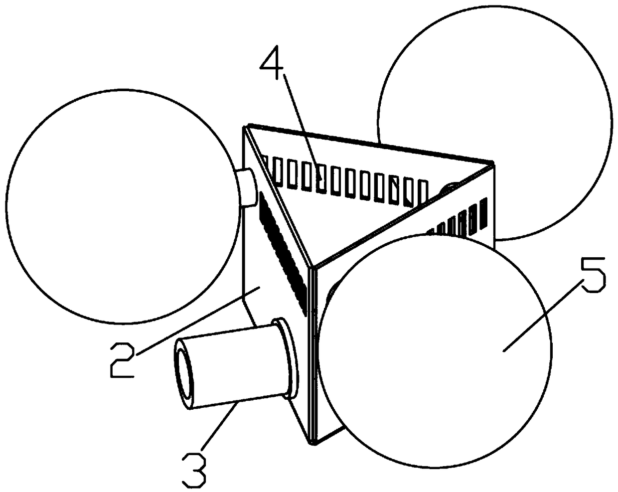
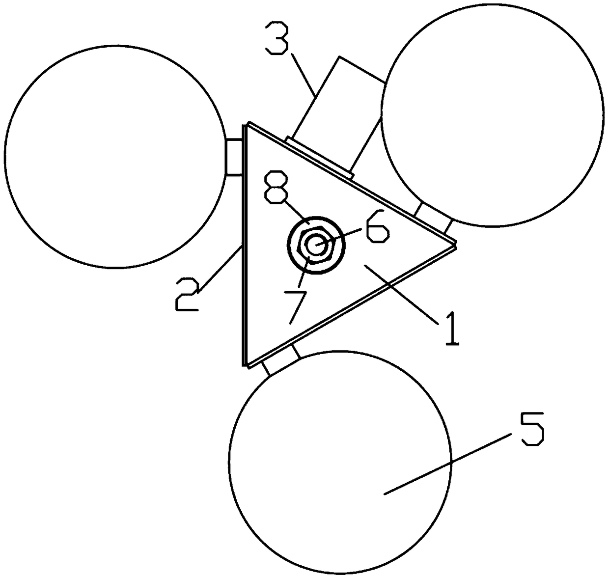
[0023] Depend on Figure 1-2 It can be seen from the illustrated embodiment that this embodiment includes a waste oil collection tank and a structure for generating uniform buoyancy in the collection tank; the waste oil collection tank includes a tank body, a waste oil discharge port 3, a waste oil collection structure and a counterweight installation structure, and the tank body includes The tank bottom wall 1 and the tank peripheral wall 2 are closed together in the circumferential direction of the tank peripheral wall 2. The bottom end of the tank peripheral wall 2 is sealed and connected with the peripheral edge of the tank bottom wall 1. The center of gravity of the tank body is located at the center point of the bottom of the waste oil collection tank. On the vertical line; the waste oil outlet 3 is arranged on the tank body, the counterweight installation structure is arranged at the center of the bottom wall 1 of the tank, and the waste oil collection structure is arran...

Embodiment 2

[0029] The difference between this embodiment and Embodiment 1 is that the counterweight installation structure includes a screw and a counterweight, the screw is vertically arranged at the center of the inner bottom of the bottom wall of the tank, and there is at least one counterweight, which is an annular body and is sleeved on the screw superior. In this way, the screw rod is vertically arranged in the inner cavity of the tank body, which is convenient for adjusting the weight of the tank body at any time during work (the lower edge of each oil inlet 4 is located at the height of the oil slick layer) without turning the device upside down to adjust, which will affect the stability of the center of gravity of the tank body have a certain influence.

[0030] According to the shape and size of the tank body, it is determined whether the counterweight is located above or below the bottom wall of the tank, so as not to affect the stability of the tank body during the waste oil ...


PUM


Abstract

The invention discloses a waste oil discharging device for cutting fluid. The waste oil discharging device comprises a waste oil collection groove and a collection groove buoyancy uniform generation structure, wherein the waste oil collection groove comprises a groove body, a waste oil discharging opening, a waste oil collection structure and a counterweight mounting structure; the groove body comprises a groove bottom wall and a groove peripheral wall; the gravity center of the groove body is located on the vertical line passing through the bottom central point of the waste oil collection groove; the waste oil collection groove is formed in the groove body; the counterweight mounting structure is arranged at the central position of a groove bottom wall; the counterweight mounting structure is arranged along the peripheral direction of the top of the groove peripheral wall and is composed of a plurality of oil feeding openings which are annularly arranged; a liquid stopping wall is arranged between each two oil feeding openings; lower edges of the oil feeding openings are located on the same horizontal height; the collection groove buoyancy uniform generation structure comprises aplurality of floating balls with the same specification; the plurality of floating balls are fixed and annularly arranged at the periphery of the groove body; the plurality of floating balls are arrayed in the peripheral direction at equal distance, and uniform buoyancy on the groove body is generated. The waste oil discharging device for the cutting fluid has the characteristics of high waste oilremoving efficiency, stable and reliable work, capability of continuously working and the like.

Description

technical field [0001] The invention relates to the technical field of cutting fluid purification. Background technique [0002] During the processing of the workpiece by the machine tool, wear and high temperature will be generated due to high-speed friction between the tool and the workpiece. In order to reduce friction and reduce the high temperature generated by friction, when processing the workpiece, it is necessary to continuously spray the contact parts of the tool and the workpiece Cutting fluid, cutting fluid is recycled through the cutting fluid circulation system. Due to leakage and other reasons, it is inevitable that some machine tool lubricating oil and hydraulic oil will be mixed into the cutting fluid circulation system. As the cutting fluid circulation time continues to increase, The content of waste oil (machine lubricating oil and hydraulic oil) in the cutting fluid will increase, which will reduce the use function of the cutting fluid, weaken the lubrica...

Claims


Application Information

Patent Timeline
IPC IPC(8): B01D17/032C02F1/40C10M175/00
CPCB01D17/0214C10M175/00C02F1/40
Inventor 张敬爽杨俊学史昊天王丹王成龙丰志良苏艳杰刘一飞程磊
Owner 逸乐(廊坊)环保科技有限公司
Why Eureka
Try Eureka