Welding equipment with smearing mechanism for exhaust pipes of upper shells of air-conditioning compressors

A technology for air-conditioning compressors and exhaust pipes, applied in the field of air-conditioning compressors, can solve problems such as inability to achieve uniform smearing, uneven welding quality, poor welding results, etc., to save manpower, improve cleanliness, and avoid serious oxidation Effect

Active Publication Date: 2018-11-23
芜湖美奥机械科技有限公司
View PDF8 Cites 2 Cited by
  • Summary
  • Abstract
  • Description
  • Claims
  • Application Information

AI Technical Summary

Problems solved by technology

[0002] In the prior art, when welding the exhaust pipe of the upper casing of the air conditioner compressor, it is necessary to apply solder paste on the installation hole of the exhaust pipe of the upper casing. Generally, silver solder paste is used. The initial state of silver solder paste is powder. It needs to be stirred with water to form a thick paste, and then manually applied. The process of applying is cumbersome and inefficient. It cannot be applied evenly when applying manually , lead to different welding quality, if the solder paste is applied on the upper shell without cleaning, it will also make the application effect worse, and the solder paste will be doped with more impurities, which will make the welding effect not good

Method used


Image

  • Welding equipment with smearing mechanism for exhaust pipes of upper shells of air-conditioning compressors
  • Welding equipment with smearing mechanism for exhaust pipes of upper shells of air-conditioning compressors
  • Welding equipment with smearing mechanism for exhaust pipes of upper shells of air-conditioning compressors

Examples


Embodiment Construction

[0021] Through the description of the embodiments below, the specific implementation of the present invention includes the shape, structure, mutual position and connection relationship between the various parts, the function and working principle of each part, the manufacturing process and the operation and use method of the various components involved. etc., to make further detailed descriptions to help those skilled in the art have a more complete, accurate and in-depth understanding of the inventive concepts and technical solutions of the present invention.

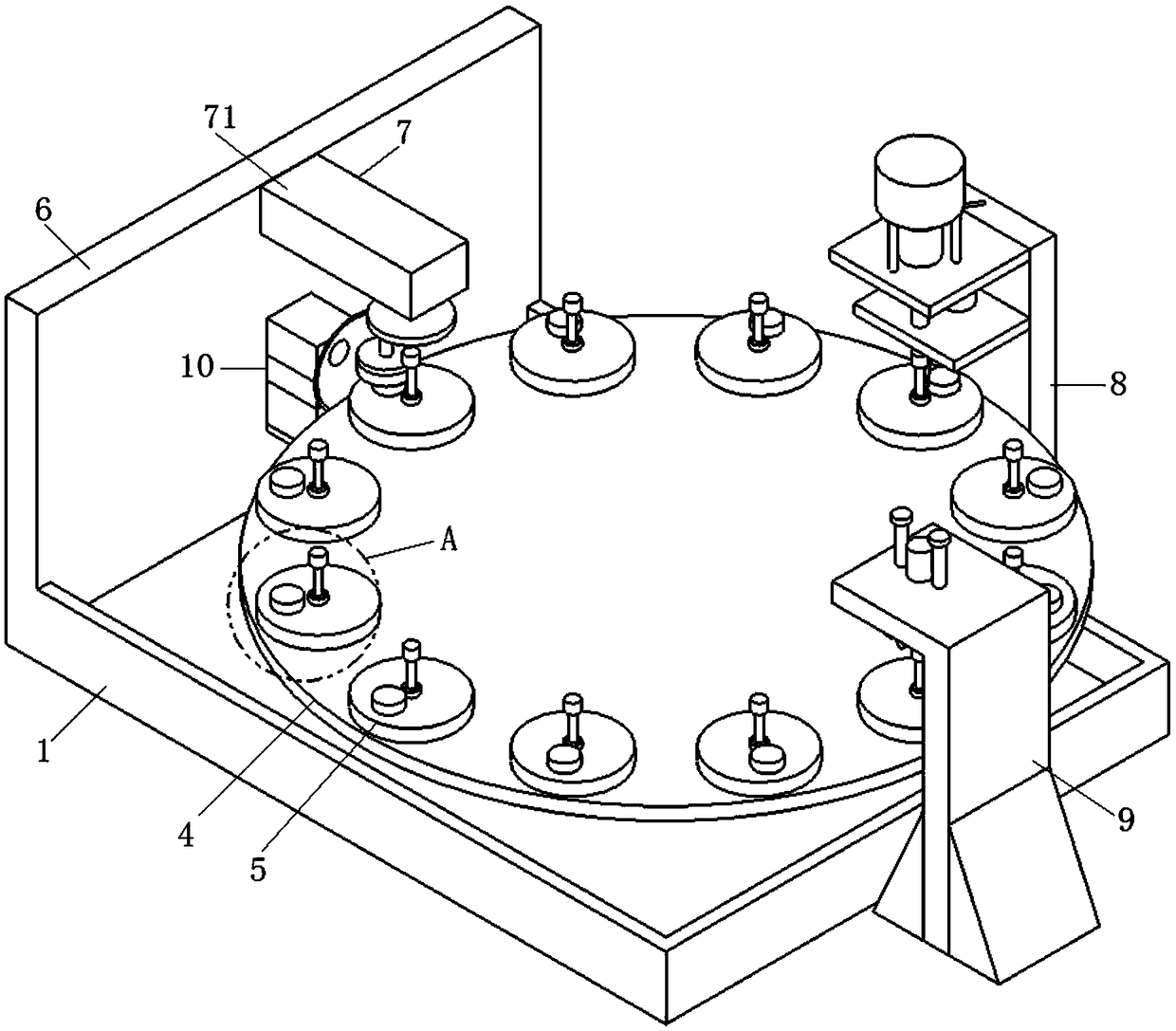
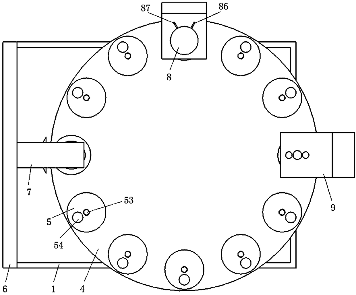
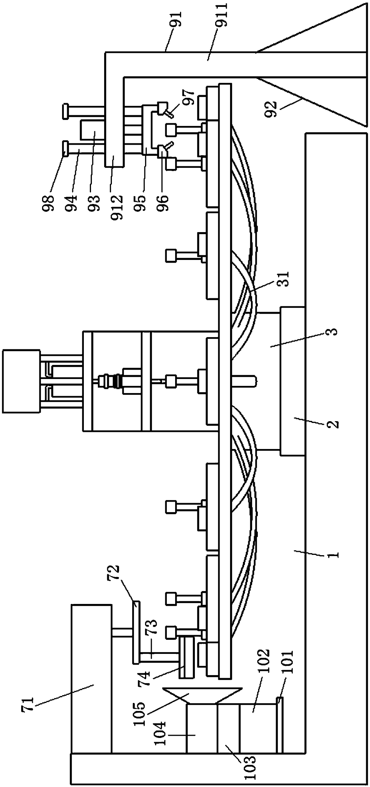
[0022] Such as Figure 1-5As shown, an air-conditioning compressor upper casing exhaust pipe welding equipment with a smearing mechanism includes a bearing pool 1, a base 2 and a controller. A base 2 is fixedly installed in the bearing pool 1, and a nitrogen supply device 3 is installed on the base 2. , the base 2 is provided with a stepping motor that drives the rotation of the nitrogen gas supply device 3, and the up...


PUM


Abstract

The invention discloses welding equipment with a smearing mechanism for exhaust pipes of upper shells of air-conditioning compressors. The welding equipment comprise a bearing pond and controllers. Abase, a nitrogen supply device and a worktable are sequentially arranged in the bearing pond from bottom to top, a plurality of base plates are arranged on the worktable, clearing stations, smearing stations and welding stations are arranged on the bearing pond, a support plate is arranged at the end, which is close to the clearing stations, of the bearing pond, a clearing mechanism and a dust collection mechanism are arranged on the support plate, the smearing mechanism is arranged on the side, which is close to the smearing stations, of the bearing pond, a welding mechanism is arranged on the side, which is close to the welding stations, of the bearing pond, gas outlet assemblies are arranged on the base plates and are connected with the nitrogen supply device by nitrogen delivery pipes,nitrogen electromagnetic valves are arranged between the nitrogen supply device and the nitrogen delivery pipes, and stepper motors, the nitrogen electromagnetic valves, the nitrogen supply device, the clearing mechanism, the smearing mechanism and the welding mechanism are electrically connected with the controllers. The welding equipment has the advantages that that welding paste can be automatically smeared by the welding equipment, accordingly, the smearing efficiency can be improved, and the brightness of the exhaust pipes and the upper shells can be guaranteed.

Description

technical field [0001] The invention belongs to the technical field of air-conditioning compressors, and in particular relates to welding equipment for an exhaust pipe of an upper casing of an air-conditioning compressor with a smearing mechanism. Background technique [0002] In the prior art, when welding the exhaust pipe of the upper casing of the air conditioner compressor, it is necessary to apply solder paste on the installation hole of the exhaust pipe of the upper casing. The solder paste generally uses silver solder paste, and the initial state of the silver solder paste is powder. It needs to be mixed with water to form a thick paste, and then manually applied. The process of applying is cumbersome and inefficient. It cannot be applied evenly when manually applying, resulting in different welding quality. The upper shell that has not been cleaned Just smearing solder paste will also make the effect of smearing worse. The solder paste will be doped with more impurit...

Claims


Application Information

Patent Timeline
Patent Type & Authority Applications(China)
IPC IPC(8): B23K3/08B23K3/00
CPCB23K3/00B23K3/08B23K3/082
Inventor 孙陈之陈富强
Owner 芜湖美奥机械科技有限公司
Why Eureka
Try Eureka