
Cooling system for numerically-controlled machine tool

A technology of cooling system and CNC machine tool, which is applied in the direction of metal processing machinery parts, maintenance and safety accessories, measuring/indicating equipment, etc., which can solve the problems of automatic adjustment of processing heat, inability to guarantee cooling, unstable surface quality of workpieces, etc., to achieve guaranteed The quality of the workpiece and the effect of ensuring effective cooling

Active Publication Date: 2018-11-23
温州市职业中等专业学校
View PDF8 Cites 9 Cited by
  • Summary
  • Abstract
  • Description
  • Claims
  • Application Information

AI Technical Summary

Problems solved by technology

[0004] In the process of workpiece processing, traditional CNC machine tools often open the coolant so that the pipes are aligned with the workpiece to cool the workpiece, but the coolant is sprayed at the same speed and cannot be automatically adjusted according to the level of processing heat, so there is no guarantee Better cooling when it is hotter, the surface quality of the workpiece will be locally unstable

Method used


Image

  • Cooling system for numerically-controlled machine tool
  • Cooling system for numerically-controlled machine tool
  • Cooling system for numerically-controlled machine tool

Examples


Embodiment Construction

[0029] The following is further described in detail through specific implementation methods:

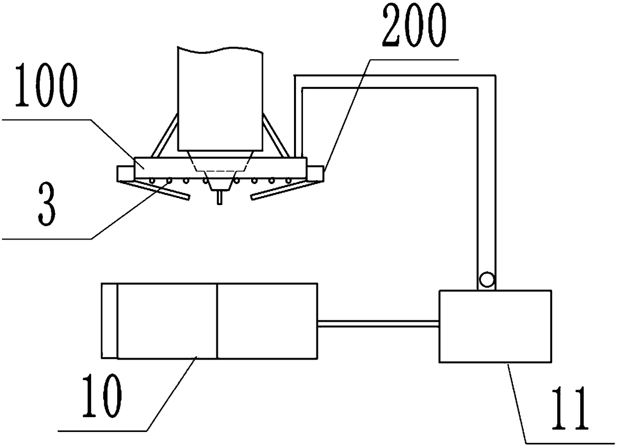
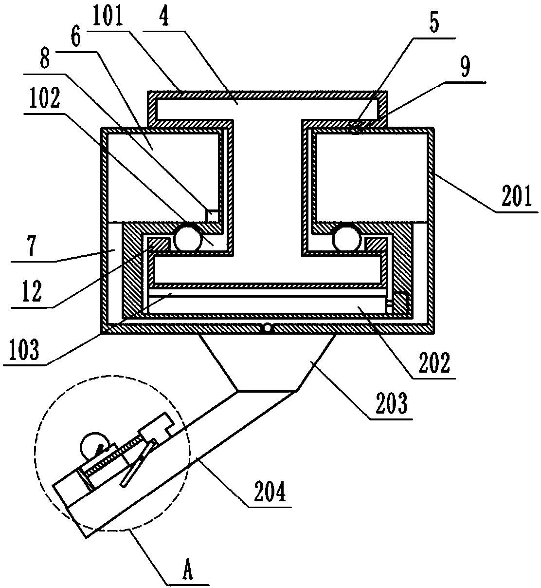
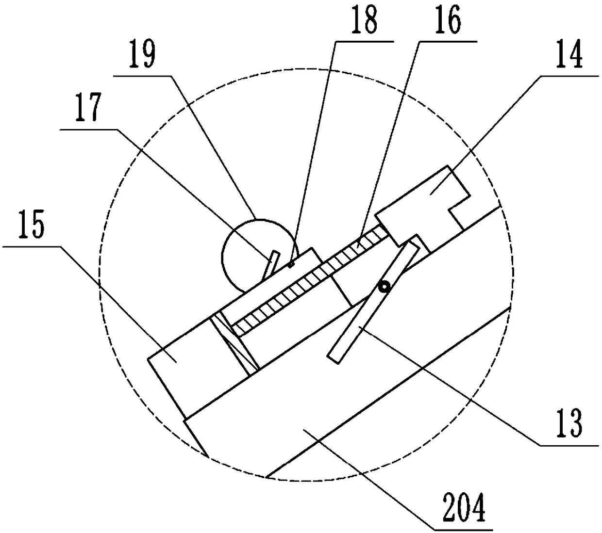
[0030] The reference signs in the drawings of the description include: ring guide rail 100, upper end surface 101, groove 102, lower end surface 103, motion mechanism 200, buckle ring 201, gear 202, connecting plate 203, nozzle 204, temperature sensor 3, cavity 4. The first solenoid valve 5, inner cavity 6, delivery channel 7, liquid level sensor 8, second solenoid valve 9, recovery tank 10, liquid storage tank 11, annular baffle 12, baffle 13, special-shaped air bag 14, cylinder Body 15, piston rod 16, first movable plate 17, first limiting block 18, filter screen 19.

[0031] Such as figure 1 As shown, a cooling system for a numerically controlled machine tool of the present invention includes an annular guide rail 100 and a motion mechanism 200; the annular guide rail 100 is fixed on the machine tool through a bracket, such as figure 2 As shown, the ring guide rail 100 is I-sha...


PUM


Abstract

The invention discloses a cooling system for a numerically-controlled machine tool and relates to the field of numerically-controlled machine tool equipment. The cooling system comprises an annular guide rail and a moving mechanism. Multiple temperature sensors are arranged on the lower portion of the annular guide rail. The annular guide rail is internally provided with a cavity. A liquid inlet pipe is arranged on the annular guide rail, wherein the liquid inlet pipe communicates with the cavity. The wall of the cavity is provided with a first solenoid valve. An infrared sensor is arranged atone side of the first solenoid valve. A buckling ring is internally provided with an inner cavity. A conveying channel is formed in the buckling ring and a connecting plate. The conveying channel enables a spray head to communicate with the inner cavity. A water pump is arranged at the connection position of the conveying channel and the inner cavity. The inner cavity is internally provided witha liquid level sensor. The wall of the inner cavity of the buckling ring is provided with a second solenoid valve. The second solenoid valve can be opposite to the first solenoid valve in position. Bymeans of the cooling system, the problem that in the workpiece machining process of a traditional numerically-controlled machine tool, the spray flow of cooling liquid cannot be adjusted automatically according to the machining heat quantity is solved; and the cooling system is mainly used for guaranteeing the cooling effect and workpiece quality.

Description

technical field [0001] The invention relates to the field of numerical control machine tool equipment, in particular to a cooling system of a numerical control machine tool. Background technique [0002] With the development of numerical control technology, high-speed, high-precision numerical control machine tool processing has replaced many manual processing. The improvement of the difficulty and precision of workpiece processing not only drives the transformation of processing technology, but also leads to the popularization and rapid development of coolant. Machine tool processing uses the relative movement between the tool and the workpiece to cause elastic and plastic deformation of the workpiece to achieve the purpose of metal processing. During the processing, due to the friction between the tool and the workpiece, a large amount of heat will be generated in the processing area. If the heat is not dissipated in time, the tool and the workpiece will be damaged, which ...

Claims


Application Information

Patent Timeline
IPC IPC(8): B23Q11/10B23Q17/09
CPCB23Q11/1038B23Q11/1069B23Q17/0985
Inventor 刘金武姜晓红
Owner 温州市职业中等专业学校
Learn More