A lamp punching device with automatic adjustment of clamps for production line

A technology of automatic adjustment and punching device, applied in metal processing and other directions, can solve the problems of difficult adjustment of fixture distance, rupture of lamp housing pressure, time-consuming and labor-intensive, etc., to ensure work continuity, save processing time, and improve work efficiency. Effect

Active Publication Date: 2020-11-27
敖慧
View PDF6 Cites 0 Cited by
  • Summary
  • Abstract
  • Description
  • Claims
  • Application Information

AI Technical Summary

Problems solved by technology

[0002] During the production process of lamps and lanterns, it is often necessary to use a punching device to punch holes in the lamp housing, bottom plate and other objects. Since the lamp housings must be fixed with fixtures during the drilling process, it is necessary to set up a punching machine separately after the lamp housings are backlogged. The hole process leads to uncontinuous production, and it is difficult to adjust the distance between the clamps during the drilling process, and cannot adapt to objects of different heights in time, and the punching device needs to be manually adjusted and loosened the clamps, resulting in excessive pressure on the lamp housing and rupture, requiring adjustment of the clamps again Loosening the object is time-consuming and labor-intensive, so a punching device that automatically adjusts and adapts to the production line is needed

Method used


Image

  • A lamp punching device with automatic adjustment of clamps for production line
  • A lamp punching device with automatic adjustment of clamps for production line
  • A lamp punching device with automatic adjustment of clamps for production line

Examples


Embodiment Construction

[0017] The following will clearly and completely describe the technical solutions in the embodiments of the present invention with reference to the accompanying drawings in the embodiments of the present invention. Obviously, the described embodiments are only some, not all, embodiments of the present invention. Based on the embodiments of the present invention, all other embodiments obtained by persons of ordinary skill in the art without making creative efforts belong to the protection scope of the present invention.

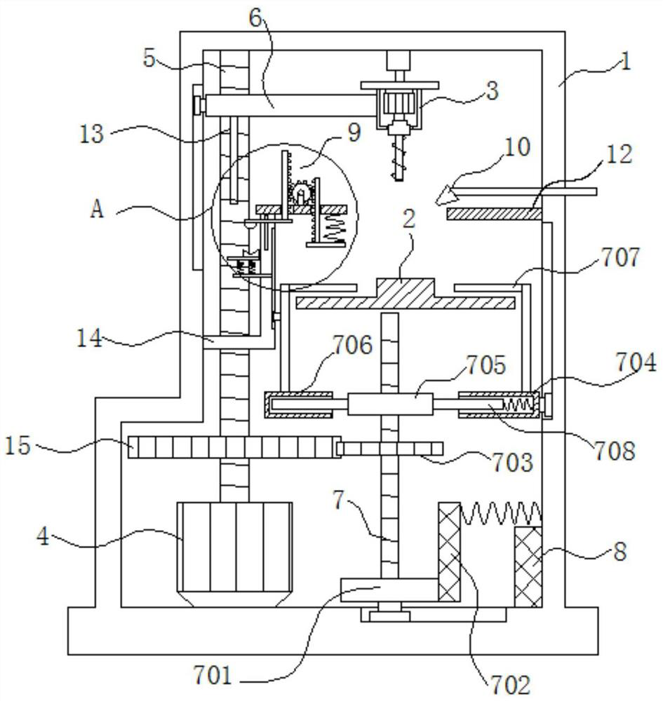
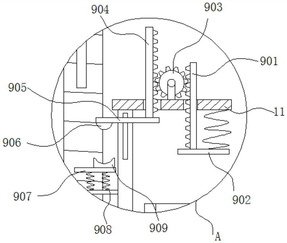
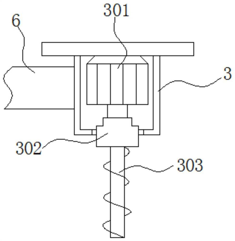
[0018] see Figure 1-3 , the present invention provides a technical solution: a lamp punching device with automatic adjustment of clamps for a production line, including a device frame 1, a conveyor belt 2 and a punching head 3, the conveyor belt 2 moves through the device frame 1, and both ends of the conveyor belt 2 are Connected with a power unit, the inner top wall of the device frame 1 is connected with a punching head 3 through a telescopic rod, and the ...


PUM


Abstract

The invention discloses a lamp punching device for automatic adjustment of a fixture for a production line. The device comprises a device frame, a conveying belt and a punching head; the conveying belt movably penetrates through the device frame; the two ends of the conveying belt are connected with power devices; the punching head is connected to the inner top wall of the device frame through anextension rod; a first screw sleeve is fixed on the side wall of the punching head; through combination of the punching head, a second motor and a clamping device, the quick punching of the lamp device is effectively realized without needing manual placement, clamping and fixation; and an electromagnet can timely absorb a first gear to deviate from a second gear to prevent a top plate from continuously moving up to excessively extrude a lamp shell to damage the lamp shell, so that the working continuity of the punching device is effectively guaranteed, the quick punching and the quick conveying of the lamp shell are realized, the machining time is effectively saved, and the working efficiency is improved.

Description

technical field [0001] The invention relates to the technical field of lamp production, in particular to a lamp punching device for automatic adjustment of fixtures used in a production line. Background technique [0002] During the production process of lamps and lanterns, it is often necessary to use a punching device to punch holes in the lamp housing, bottom plate and other objects. Since the lamp housings must be fixed with fixtures during the drilling process, it is necessary to set up a punching machine separately after the lamp housings are backlogged. The hole process leads to uncontinuous production, and it is difficult to adjust the distance between the clamps during the drilling process, and cannot adapt to objects of different heights in time, and the punching device needs to be manually adjusted and loosened the clamps, resulting in excessive pressure on the lamp housing and rupture, requiring adjustment of the clamps again Loosening the object is time-consumin...

Claims


Application Information

Patent Timeline
Patent Type & Authority Patents(China)
IPC IPC(8): B26F1/16B26D7/02B26D7/18
CPCB26D7/02B26D7/1854B26F1/16
Inventor 敖慧
Owner 敖慧
Why Eureka
Try Eureka