
A steel cover automatic engraving machine

A technology of engraving machine and steel cover, applied in printing, stamping, etc., can solve the problems of lower overall efficiency, high use cost, and slow stamping stroke speed

Active Publication Date: 2020-08-04
嘉兴晟源工业设计有限公司
View PDF9 Cites 0 Cited by
  • Summary
  • Abstract
  • Description
  • Claims
  • Application Information

AI Technical Summary

Problems solved by technology

[0002] The steel cover is a round cover made of stainless steel, and its specifications are adjusted according to the actual use. At present, after the steel cover is prepared, it needs to engrave the relevant fonts on the top surface of the cover before leaving the factory. One process uses manual loading and unloading to assist marking, which increases the cost of personnel use, and for the stamping equipment in steel cover marking, the speed of the stamping stroke is generally slow. The steel cover will be damaged due to the impact of the stroke too fast, resulting in defective products, but in this case, the overall efficiency of mass production will be greatly reduced due to the problem of stamping speed

Method used


Image

  • A steel cover automatic engraving machine
  • A steel cover automatic engraving machine
  • A steel cover automatic engraving machine

Examples


Embodiment Construction

[0026] Below in conjunction with accompanying drawing and embodiment of description, specific embodiment of the present invention is described in further detail:

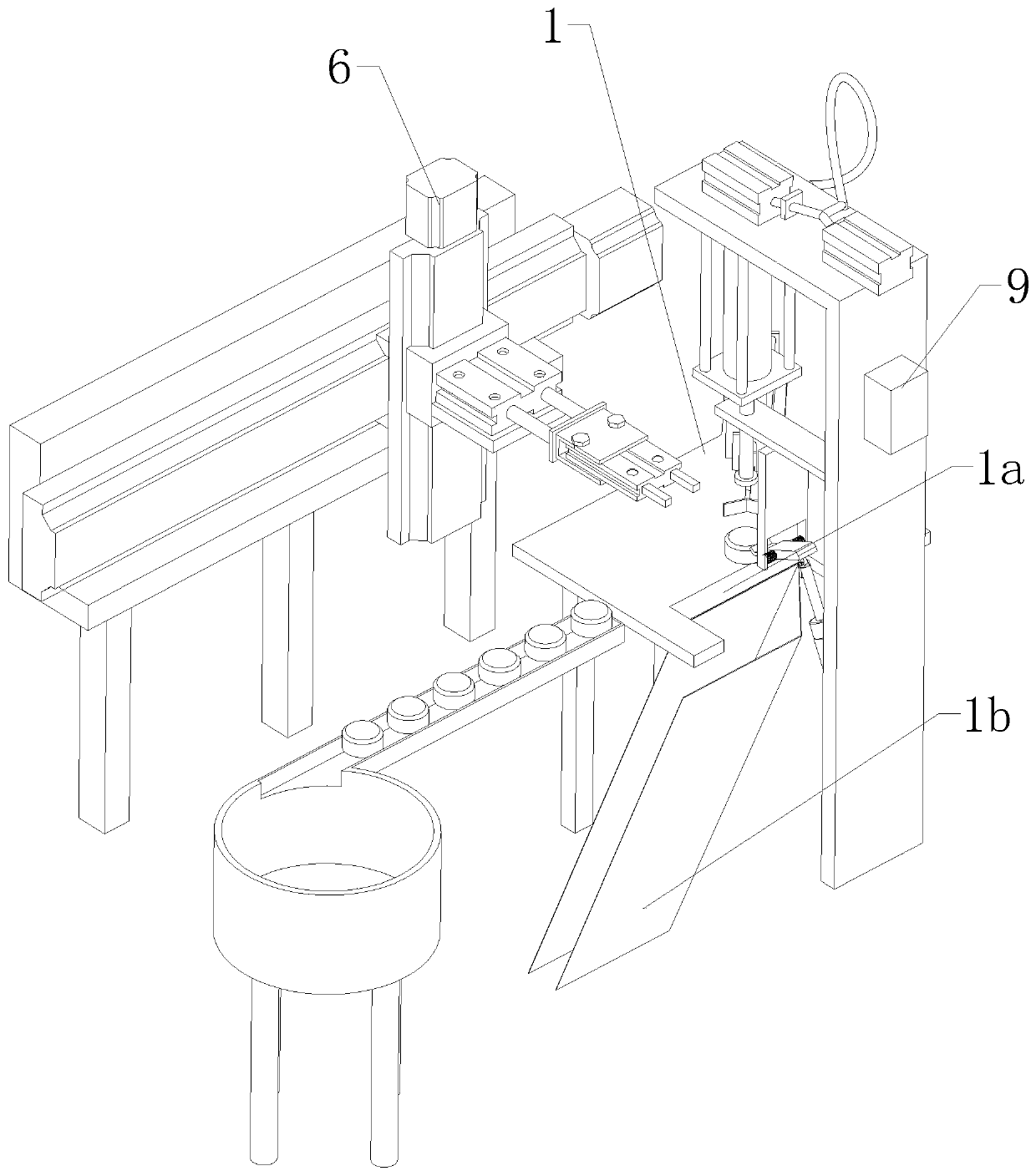
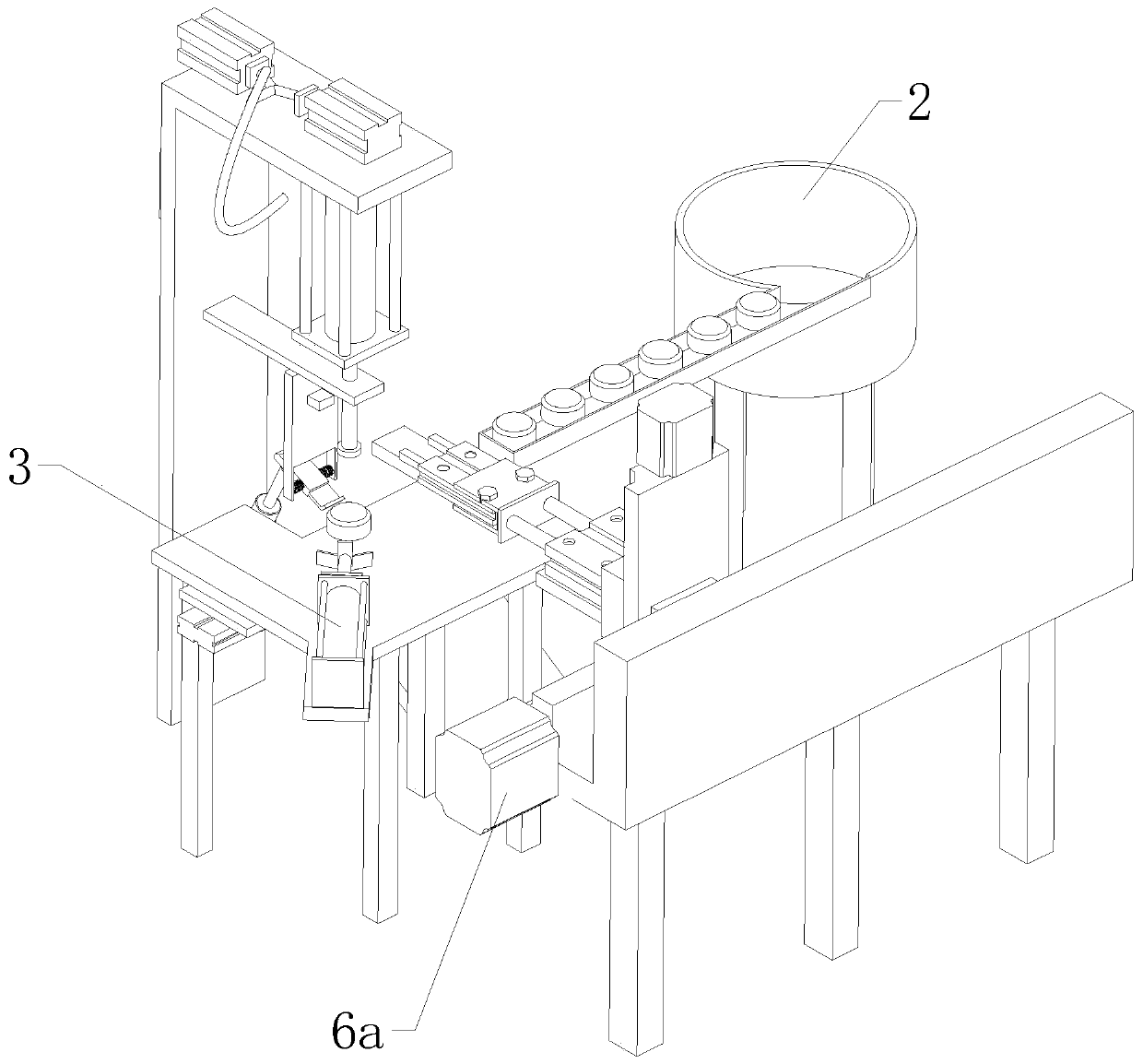
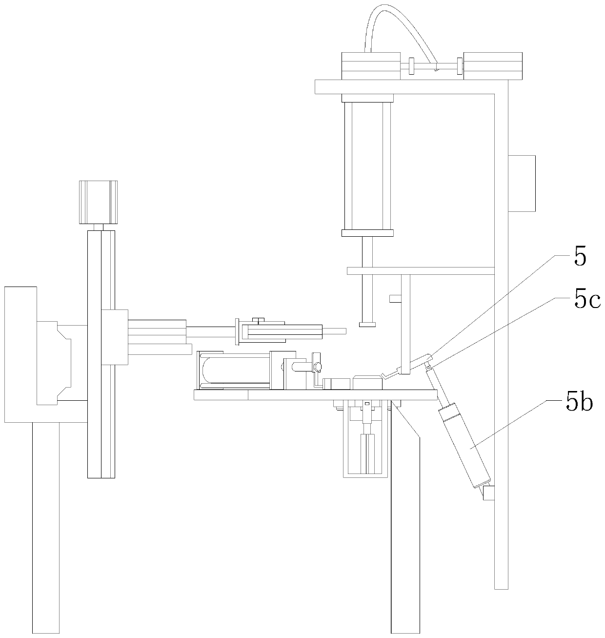
[0027] refer to Figure 1 to Figure 9 The shown automatic marking machine for steel caps includes a marking table 1 and a vibrating feeder 2 for conveying steel caps 8, and also includes a controller 9, a discharge device, a stamping marking device arranged above the marking table 1 and An anti-sway device for pressing down on one side of the steel cover 8, a feeding device is provided on the outside of the marking table 1, and the feeding device includes a transmission assembly and a feed cylinder 6b arranged on the output end of the transmission assembly. The output direction of the feed cylinder 6b is towards the downstream end of the vibrating feeder 2, and a through hole 7 is opened on the top of the marking table 1, and the through hole 7 runs through the marking table 1, and a lower mold inner liner 7a and an...


PUM


Abstract

The invention relates to the field of steel cover processing, in particular to an automatic marking machine for steel covers. The marking machine comprises a marking table and a vibrating feeder, wherein the vibrating feeder is used for conveying the steel covers, and the marking machine further comprises a controller, a discharging device, a stamping and marking device and an anti-shaking device;the outer side of the marking table is provided with a feeding device, the feeding device comprises a transmission assembly and a feeding air cylinder, and the output direction of the feeding air cylinder faces the downstream end of the vibrating feeder; a through hole is formed in the top of the marking table, and a lower die inner lining block and a lining air cylinder are arranged below the through hole; and the stamping and marking device comprises a stamping air cylinder and a position sensor, an L-shaped machine base is arranged beside the marking table, the stamping air cylinder is arranged at the top of the L-shaped machine base, the position sensor is arranged at the position, close to the top of the marking table, of the L-shaped machine base, and the position sensor is electrically connected with a controller. According to the marking machine, the steel covers can be automatically fed and positioned, moreover, stamping stroke force of the stamping air cylinder used for marking are slowed down gradually, so that the overall efficiency is remarkably improved in batch production.

Description

technical field [0001] The invention relates to the field of steel cover processing, in particular to an automatic marking machine for steel covers. Background technique [0002] The steel cover is a round cover made of stainless steel, and its specifications are adjusted according to the actual use. At present, after the steel cover is prepared, it needs to engrave the relevant fonts on the top surface of the cover before leaving the factory. One process uses manual loading and unloading to assist marking, which increases the cost of personnel use, and for the stamping equipment in steel cover marking, the speed of the stamping stroke is generally slow. The steel cover will be damaged due to the impact force of the stroke too fast, resulting in defective products, but in this case, the overall efficiency of mass production will be greatly reduced due to the problem of stamping speed. Contents of the invention [0003] The object of the present invention is to provide an ...

Claims


Application Information

Patent Timeline
Patent Type & Authority Patents(China)
IPC IPC(8): B41K3/04B41K3/62B41K3/64
CPCB41K3/04B41K3/62B41K3/64
Inventor 栾友祥
Owner 嘉兴晟源工业设计有限公司
Learn More