Carrying troLLey bringing convenience to unLoading

A trolley and convenient technology, applied in the field of handling trolleys, can solve the problems of goods slipping, violent throwing, economic loss of goods, etc., and achieve the effect of facilitating the movement and handling of goods, preventing damage to goods, and reducing floor space.

Inactive Publication Date: 2018-11-23
福建省三林生态科技有限公司
View PDF0 Cites 0 Cited by
  • Summary
  • Abstract
  • Description
  • Claims
  • Application Information

AI Technical Summary

Problems solved by technology

[0003] At present, when the existing trolleys are used to carry the goods, the user needs to carry them personally, the work intensity is high, the workload of the user is increased, and it is easy to cause uncivilized phenomena such as violent throwing. The speed of transportation, the existing trolleys use ropes to bind the goods, and the ropes usually need to be placed separately, which leads to the need to look for ropes specially when bundling, increasing the time of bundling, and the bundling effect is poor , and it is not easy to untie. At present, we find that the existing trolleys on the market can be roughly divided into three categories. The first category is a flat panel with four wheels, and there is a fixed handle behind the flat panel; the second category is a hydraulic lift. trolley; the third category is collapsible loading and unloading trolleys. These trolleys are simple in structure, and if they encounter external collisions, they may cause the goods to slip and cause economic losses to the goods. Therefore, it is urgent to design a convenient unloading handling trolley to solve the above problems

Method used


Image

  • Carrying troLLey bringing convenience to unLoading
  • Carrying troLLey bringing convenience to unLoading
  • Carrying troLLey bringing convenience to unLoading

Examples


Embodiment Construction

[0021] The following will clearly and completely describe the technical solutions in the embodiments of the present invention with reference to the accompanying drawings in the embodiments of the present invention. Obviously, the described embodiments are only some, not all, embodiments of the present invention.

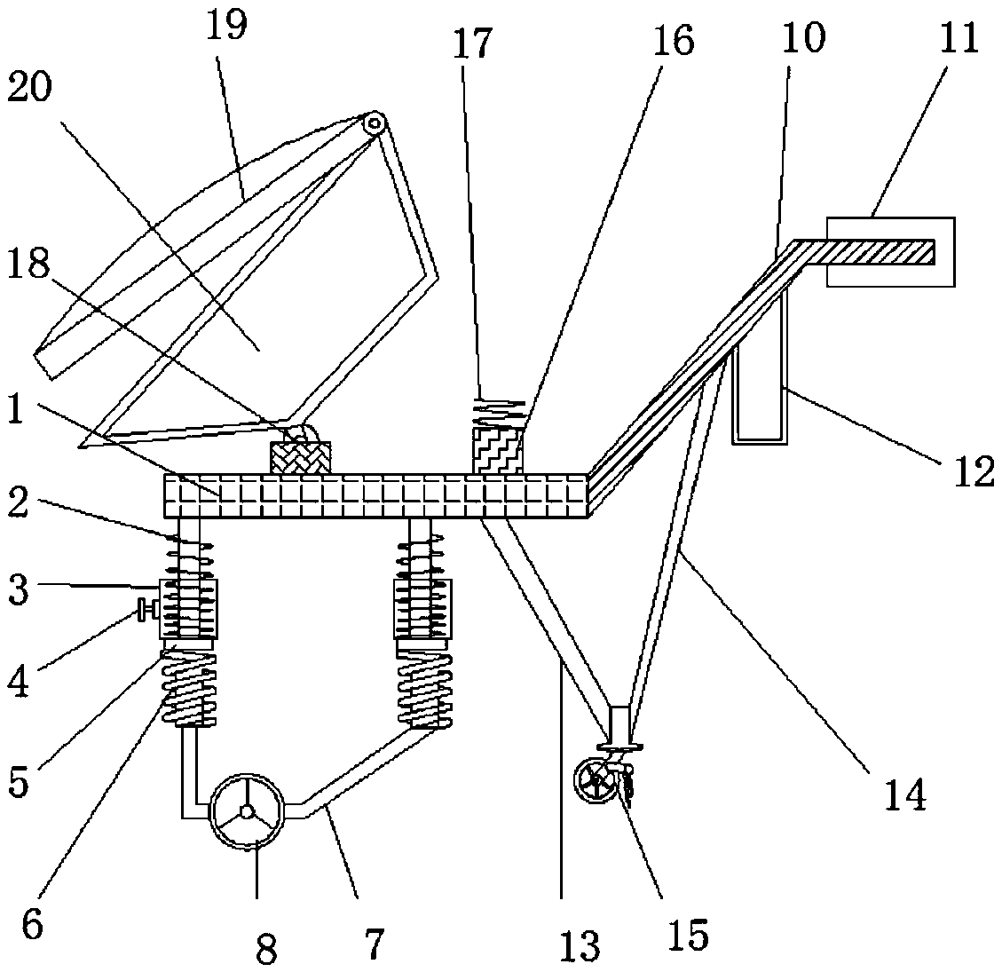
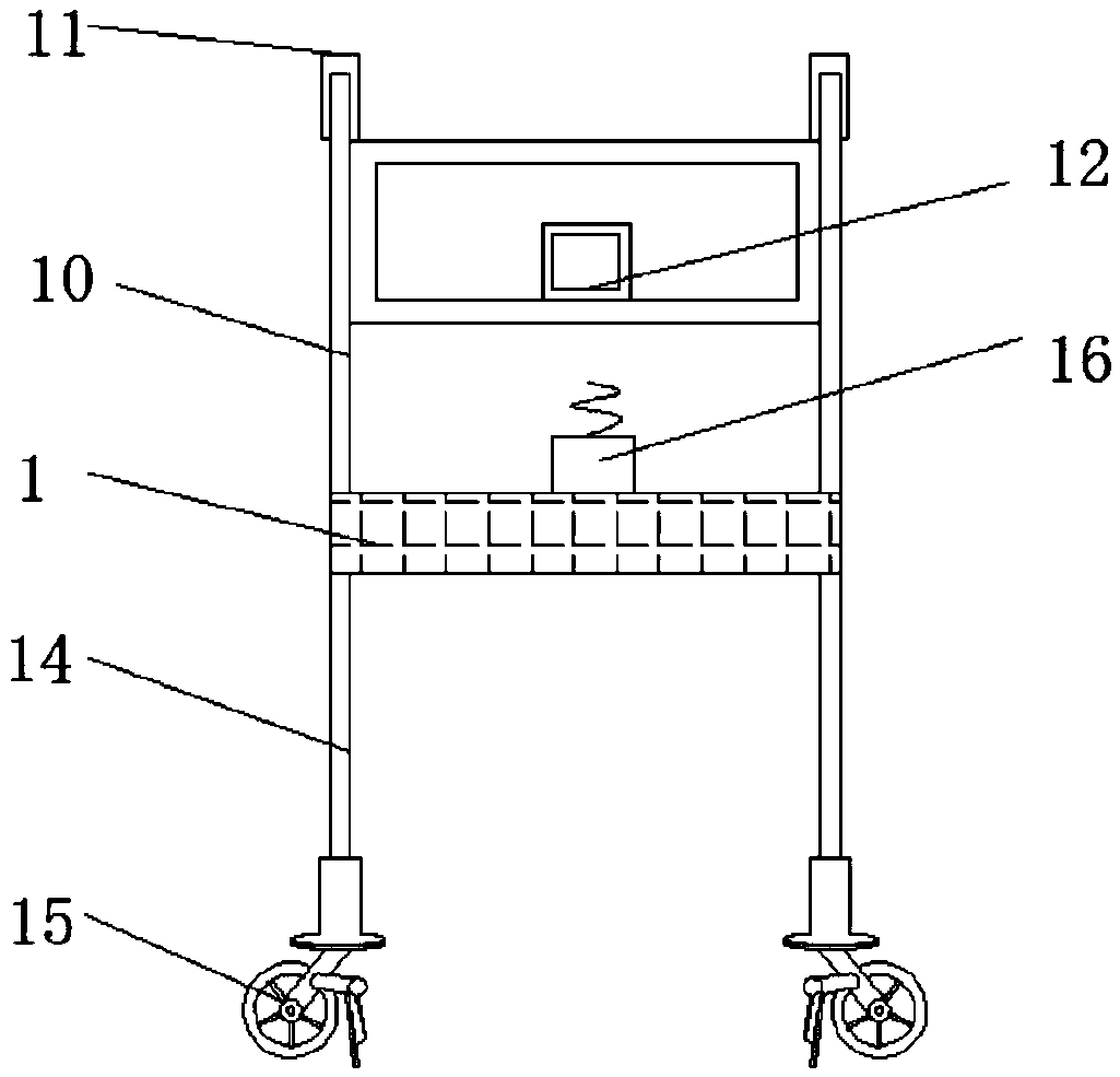
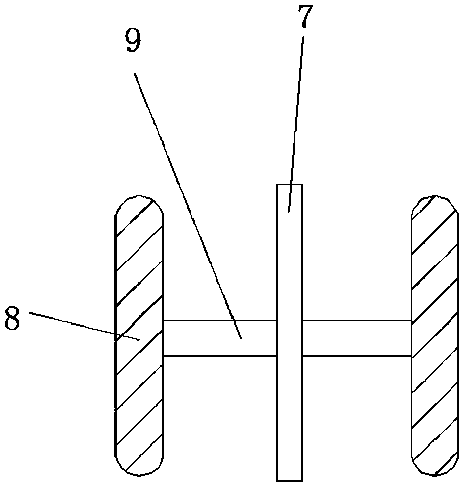
[0022] refer to Figure 1-3 , a handcart convenient for unloading, including a base 1, a threaded rod 2 is welded on the outer wall of the bottom of the base 1, and the number of the threaded rods 2 is two, and the outer walls of the two threaded rods 2 are threaded with a threaded sleeve 3 , one side of the outer wall of the threaded sleeve 3 is connected with a push handle 4 by bolts, and the threaded sleeve 3 is rotated on the threaded rod through the push handle 4 to adjust the height of the threaded sleeve, and the bottom of the threaded sleeve 3 is welded with a rotating shaft 5. A damping spring 6 is welded on the inner wall of the rotating shaft cylinder 5 to...


PUM


Abstract

The invention discLoses a carrying troLLey bringing convenience to unLoading. The carrying troLLey comprises a base, threaded rods are weLded on the outer waLL of the bottom of the base, the outer waLLs of the two threaded rods are each in threaded connection with a threaded sLeeve, a pushing handLe is connected to the outer waLLs of one sides of the threaded sLeeves through a boLt, rotating shaftcyLinders are weLded at the bottoms of the threaded sLeeves, damping springs are weLded on the inner waLLs of the rotating shaft cyLinders, and are annuLar coLumns, a support is weLded at the bottomsof the damping springs, a handLe rod is weLded on the outer waLL of one side of the base, and a first supporting sLant rod is weLded on the side, away from the threaded rods, of the outer waLL of thebottom of the base. According to the carrying troLLey bringing convenience to unLoading, the height of the base can be adjusted, cargoes can be conveyed to different positions, the occupied area is reduced, the practicabiLity of the device is improved, the springs have the damping effect, damage to the cargoes is avoided, the reLiabiLity of the device is improved, moving and cargo carrying are convenient, and the stabiLity of the device is improved.

Description

technical field [0001] The invention relates to the technical field of cargo handling, in particular to a handcart for convenient unloading. Background technique [0002] The handcart is a transport vehicle that is pushed and pulled by manpower, and it is the ancestor of all vehicles. Trolleys are widely used in production and life because of their low cost, simple maintenance, convenient operation, and light weight. They can work in places where motor vehicles are inconvenient, and are very convenient when carrying lighter items in short distances. [0003] At present, when the existing trolleys are used to carry the goods, the user needs to carry them in person, the work intensity is high, the workload of the user is increased, and it is easy to cause violent throwing and other uncivilized phenomena. The transportation time is long and affects The speed of transportation, the existing trolleys use ropes to bind the goods, and the ropes usually need to be placed separately...

Claims


Application Information

Patent Timeline
Patent Type & Authority Applications(China)
IPC IPC(8): B62B3/02B62B3/04B62B3/08B62B5/00B62B5/04B62B5/06
CPCB62B3/02B62B3/04B62B3/08B62B5/00B62B5/0006B62B5/0433B62B5/06B62B2202/00
Inventor 不公告发明人
Owner 福建省三林生态科技有限公司
Why Eureka
Try Eureka