Lifting fin plate stabilizing system

A technology for stabilizing the system and raising and lowering fins, which is applied to ship components, ships, transportation and packaging, etc., and can solve problems such as complex processes, broken hinges, and failure of lowered fins

Pending Publication Date: 2018-11-23
SHANGHAI FUXUN IND CO LTD
View PDF0 Cites 5 Cited by
  • Summary
  • Abstract
  • Description
  • Claims
  • Application Information

AI Technical Summary

Problems solved by technology

However, setting rollers or hinge systems on the liftable fins is not only a complicated process, but also the shaft may deform with the hull when the sea conditions are bad. At this time, i

Method used


Image

  • Lifting fin plate stabilizing system
  • Lifting fin plate stabilizing system
  • Lifting fin plate stabilizing system

Examples


Embodiment Construction

[0030] The following will clearly and completely describe the technical solutions in the embodiments of the present invention with reference to the accompanying drawings in the embodiments of the present invention. Obviously, the described embodiments are only some, not all, embodiments of the present invention. Based on the embodiments of the present invention, all other embodiments obtained by persons of ordinary skill in the art without making creative efforts belong to the protection scope of the present invention.

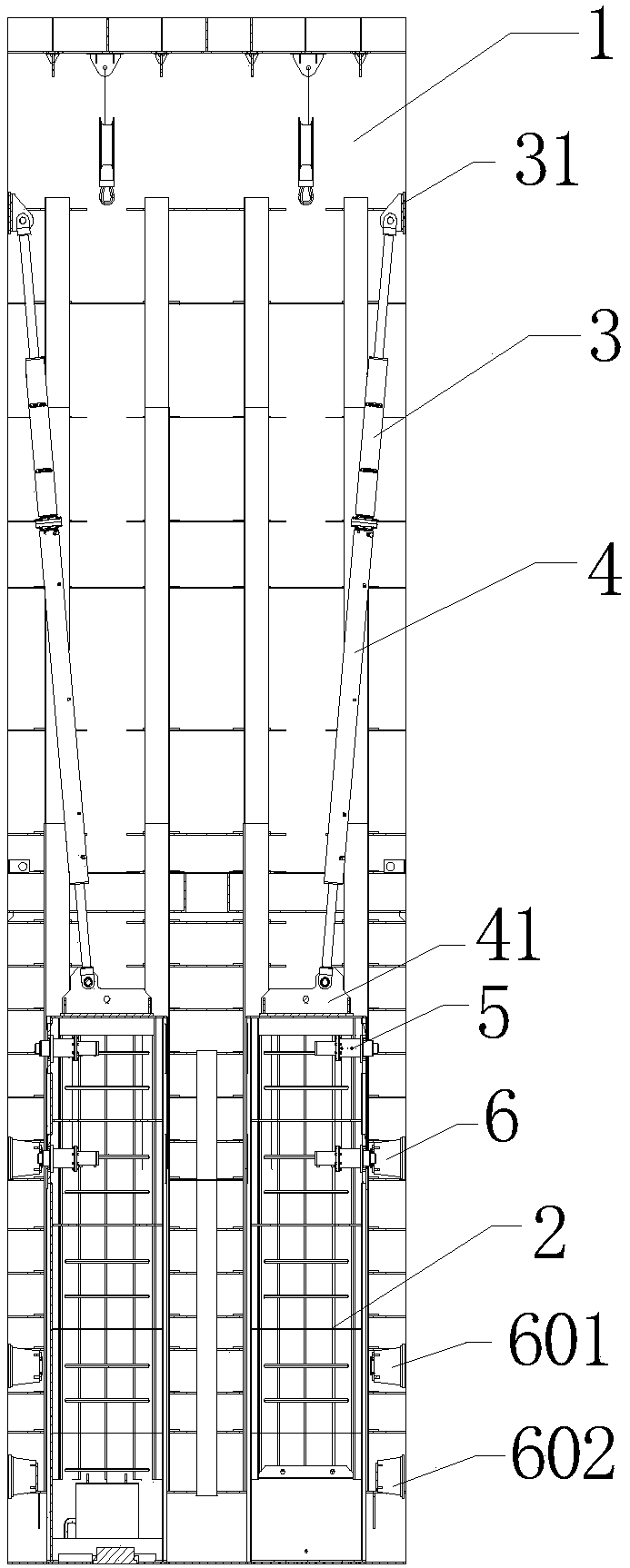
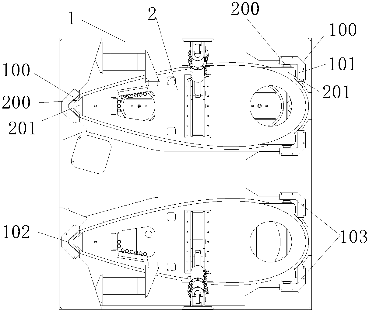
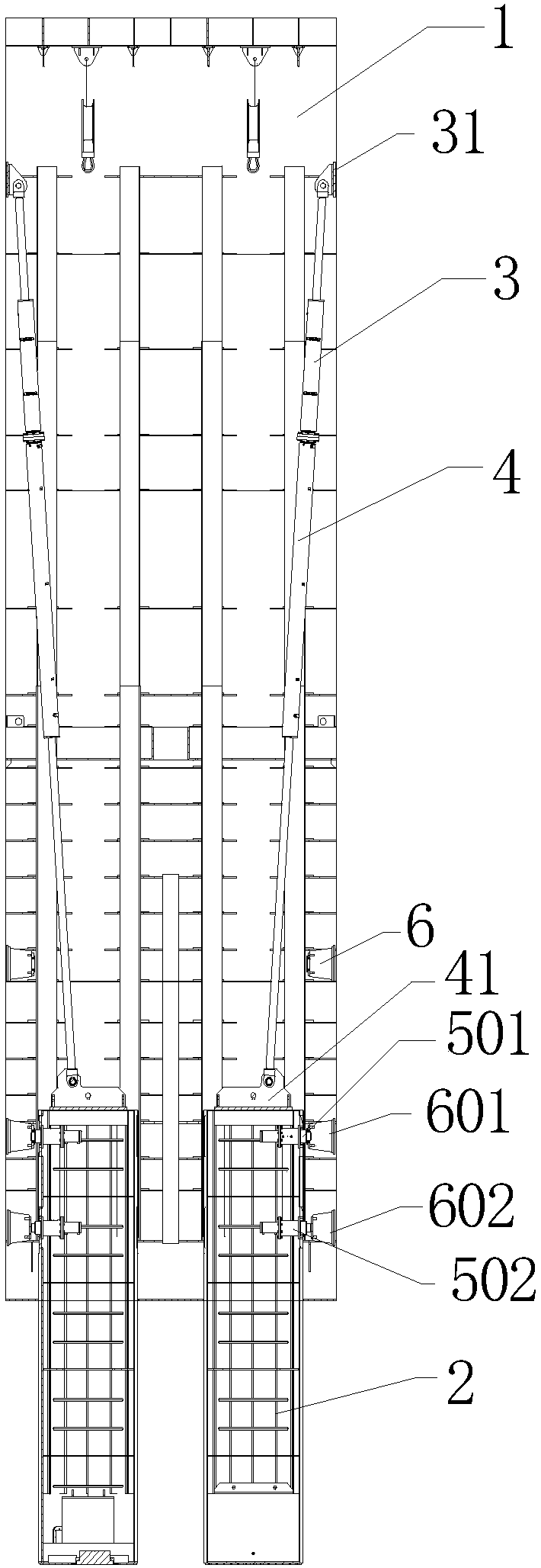
[0031] Such as figure 1 , figure 2 , image 3 , Figure 4 , Figure 5 , Figure 6 , Figure 7 , Figure 8 and Figure 9As shown, a lifting fin stabilization system includes a shaft 1 and a fin 2 located in the shaft. Above the fin 2, a bidirectional oil cylinder consisting of an upper oil cylinder 3 and a lower oil cylinder 4 is provided. One end of the upper oil cylinder 3 The other end is connected with the inner top of shaft 1 and the other end is ...


PUM


Abstract

The invention discloses a lifting fin plate stabilizing system. The system comprises a vertical well and fin plates located in the vertical well; hydraulic locking pins are arranged in the middles ofthe fin plates; grooves are formed in the tops of piston push rods of the hydraulic locking pins, and infrared emitting devices provided with power sources are embedded in the grooves; locking pin bases are arranged on the wall of the vertical well, limiting grooves are formed in the front ends of the locking pin bases, and the piston push rods can stretch into the limiting grooves for jacking; signal line through holes communicated with the outside of the locking pin bases are formed in the bottoms of the limiting grooves; infrared receiving devices are arranged in the through holes, the hydraulic locking pins are connected with a petroleum supply station, the petroleum supply station, the infrared emitting devices and the infrared receiving devices are connected with a control device through a communication line, pressure sensors are arranged in the limiting grooves and connected with the control device, the petroleum supply station comprises a hydraulic locking pin control system, and the hydraulic locking pin control system is connected with the hydraulic locking pins.

Description

technical field [0001] The invention relates to the technical field of scientific research ships, in particular to a lifting fin stabilization system. Background technique [0002] In the field of scientific research ships, the liftable fin is an important and reliable platform, and its lower end can carry a variety of detection instruments, and these detection instruments can be exempted from the influence of sea surface currents. The liftable fins are set in the shaft, which are connected to the scientific research ship through the lifting device; in the prior art, the liftable fins mainly cooperate with the shaft through the roller system or the hinge system to realize the vertical movement of the liftable fins in the shaft. Smooth movement. However, setting rollers or hinge systems on the liftable fins is not only a complicated process, but also the shaft may deform with the hull when the sea conditions are bad. At this time, it is difficult for the roller system or hin...

Claims


Application Information

Patent Timeline
IPC IPC(8): B63B17/00
CPCB63B17/00B63B2710/00
Inventor 朱洪波周宏斌
Owner SHANGHAI FUXUN IND CO LTD
Why Eureka
Try Eureka