Steel bridge deck pavement structure

A steel bridge deck and pavement technology, applied in bridges, bridge parts, bridge construction, etc., can solve the problems of increasing the constant weight of steel bridge decks, the difficulty of concrete, and the insufficient shear resistance of concrete, and can repair fracture cracks and fatigue. Damage, strong absorption and transmission of various stresses, and the effect of solving shear resistance problems

Pending Publication Date: 2018-11-23
武汉金麦特材料科技有限公司
View PDF0 Cites 4 Cited by
  • Summary
  • Abstract
  • Description
  • Claims
  • Application Information

AI Technical Summary

Problems solved by technology

[0005] The combination between ordinary SMA asphalt mastic concrete and steel bridge deck is not easy to solve, and it is easy to cause insufficient shear resistance of concrete, and the phenomenon of pavement shifting occurs, resulting in rutting and bulging;
[0006] When pavement is combined with high-performance concrete and asphalt, it is necessary to increase the shear resistance of the pavement by welding shear nails, but the welding of shear nails will increase the stress change of the steel bridge deck, and the concrete will increase the stress of the steel bridge deck. In addition, the on-site construction of concrete is likely to cause hidden dangers such as insufficient compactness of the concrete, resulting in the inability of the high-performance concrete slab and the steel bridge deck to be tightly combined. issues such as shear movement between

Method used


Image

  • Steel bridge deck pavement structure
  • Steel bridge deck pavement structure
  • Steel bridge deck pavement structure

Examples


Embodiment Construction

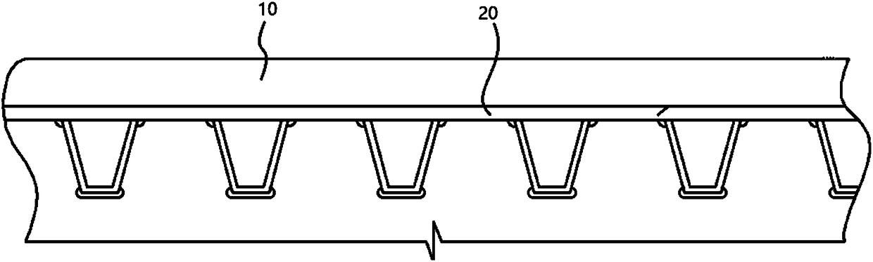
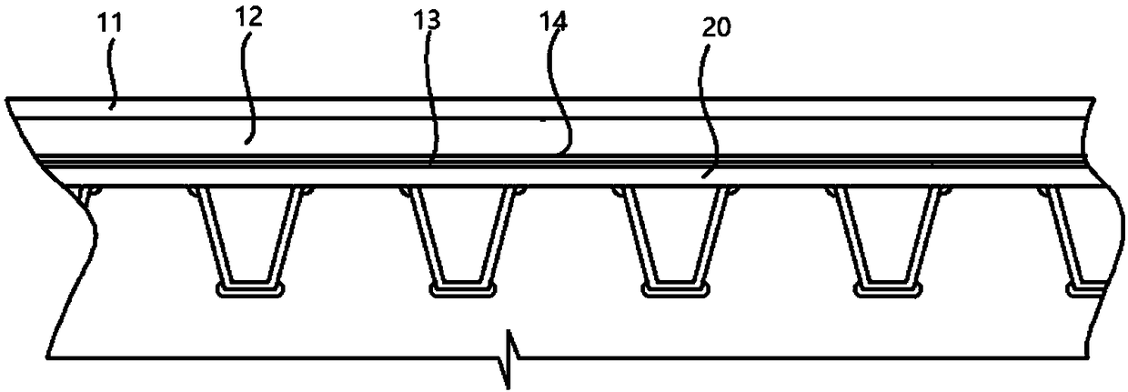
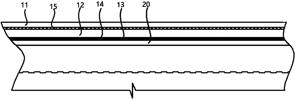
[0018] Such as figure 1 , 2 As shown, an embodiment of the present invention discloses a steel bridge deck pavement structure, including laying a composite structure 10 on a steel bridge deck 20, and the composite structure 10 includes an interface layer 13 that is laid sequentially from bottom to top and bonded to each other , Polyurethane-based fiber-reinforced material board 12 and wearing layer 11.

[0019] The interface layer 13 is formed by bonding and curing polyurethane resin and fiber material on the steel bridge deck 20 . The function of the interface layer 13 is to seal the steel bridge deck and isolate it from moisture; at the same time, it forms a layer of dense polar polymer surface so that it can be tightly bonded to the polyurethane-based fiber reinforced material plate 12; in addition, it becomes a shear stress The transfer layer enables the internal shear stress of the entire steel bridge deck 20 and the composite structure 10 to be evenly distributed in th...


PUM

PropertyMeasurementUnit
Areal densityaaaaaaaaaa

Abstract

The invention relates to the technical field of bridge deck pavement in bridge engineering and particularly discloses a steel bridge deck pavement structure. The steel bridge deck pavement structure comprises a boundary layer, a composite material layer and a wearing layer, wherein the boundary layer, the composite material layer and the wearing layer are paved from bottom to top and adhere mutually; the boundary layer is a polyurethane resin layer which fibrous materials adhere to; the composite material layer is a polyurethane-base fibrous reinforcement material plate layer; the wearing layer is a concrete wearing layer. Through bonding of the polyurethane-base fibrous reinforcement material plate layer, the boundary layer and the wearing layer, the overall bending-resistant anti-pressure capacity of a steel bridge deck is enhanced, the problems that steel plates between steel bridge deck reinforcement ribbed plates deform and generate cracks, and the shear capacity of the steel bridge deck and a pavement layer is poor can be solved, the breakage cracks and fatigue damage of the steel bridge deck can be repaired, construction is convenient and rapid, and the maintenance period during bridge deck pavement construction is shortened.

Description

technical field [0001] The invention relates to the technical field of bridge deck pavement of bridge engineering, in particular to a steel bridge deck pavement structure. Background technique [0002] At present, steel bridges, especially orthotropic steel decks, are more and more widely used. The existing bridge deck pavement schemes mainly include: 1. Poured asphalt concrete pavement; 2. Epoxy asphalt concrete pavement; 3. Ordinary SMA asphalt mastic concrete pavement; 4. Combined pavement of high performance concrete and asphalt wear layer, etc. Each of the above options has its disadvantages: [0003] Poured asphalt concrete pavement is easy to cause expansion and deformation of the steel bridge deck due to the high temperature of the asphalt during construction and pouring. Therefore, the expansion and ductility of the pavement material is required to be high, otherwise cracks in the pavement layer will easily appear; [0004] Epoxy asphalt concrete is more brittle a...

Claims


Application Information

Patent Timeline
IPC IPC(8): E01D19/12E01D21/00
CPCE01D19/125E01D21/00
Inventor 欧阳贞祥徐松林乔松林陶国强李文翚
Owner 武汉金麦特材料科技有限公司
Why Eureka
Try Eureka