
The method of the lower guide beam type fixed-point hoisting bridge erecting machine passing through the tunnel based on the front outrigger

A technology of front outriggers and bridge erecting machines, which is applied in the direction of bridges, bridge construction, erection/assembly of bridges, etc. It can solve the problems of heavy unloading workload, disintegration through tunnels, and complicated operations, and achieve less unloading workload, Good working condition adaptability and simple structure

Active Publication Date: 2020-04-07
袁攀峰
View PDF5 Cites 0 Cited by
  • Summary
  • Abstract
  • Description
  • Claims
  • Application Information

AI Technical Summary

Problems solved by technology

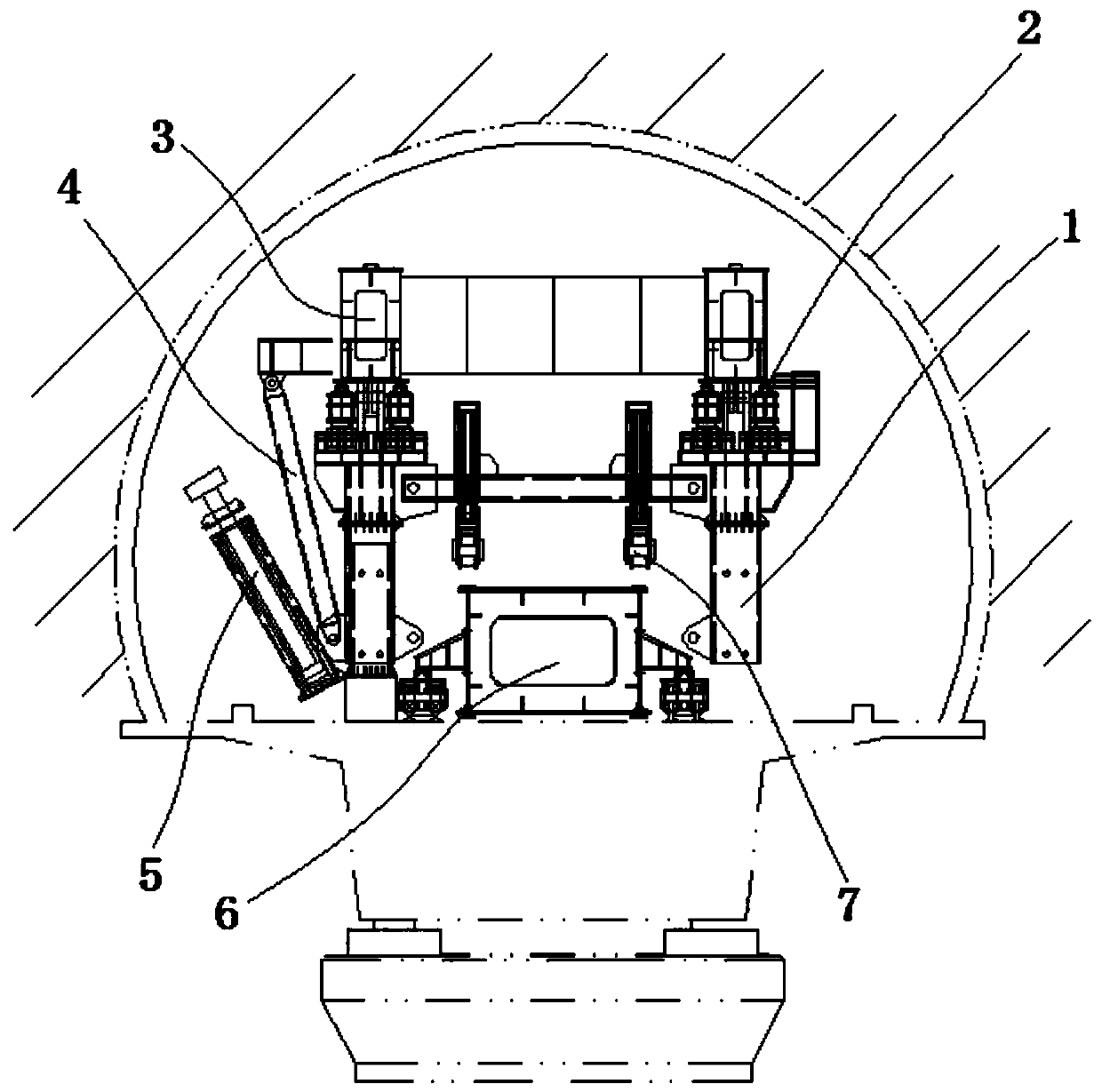
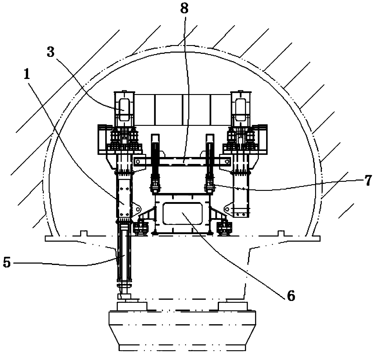
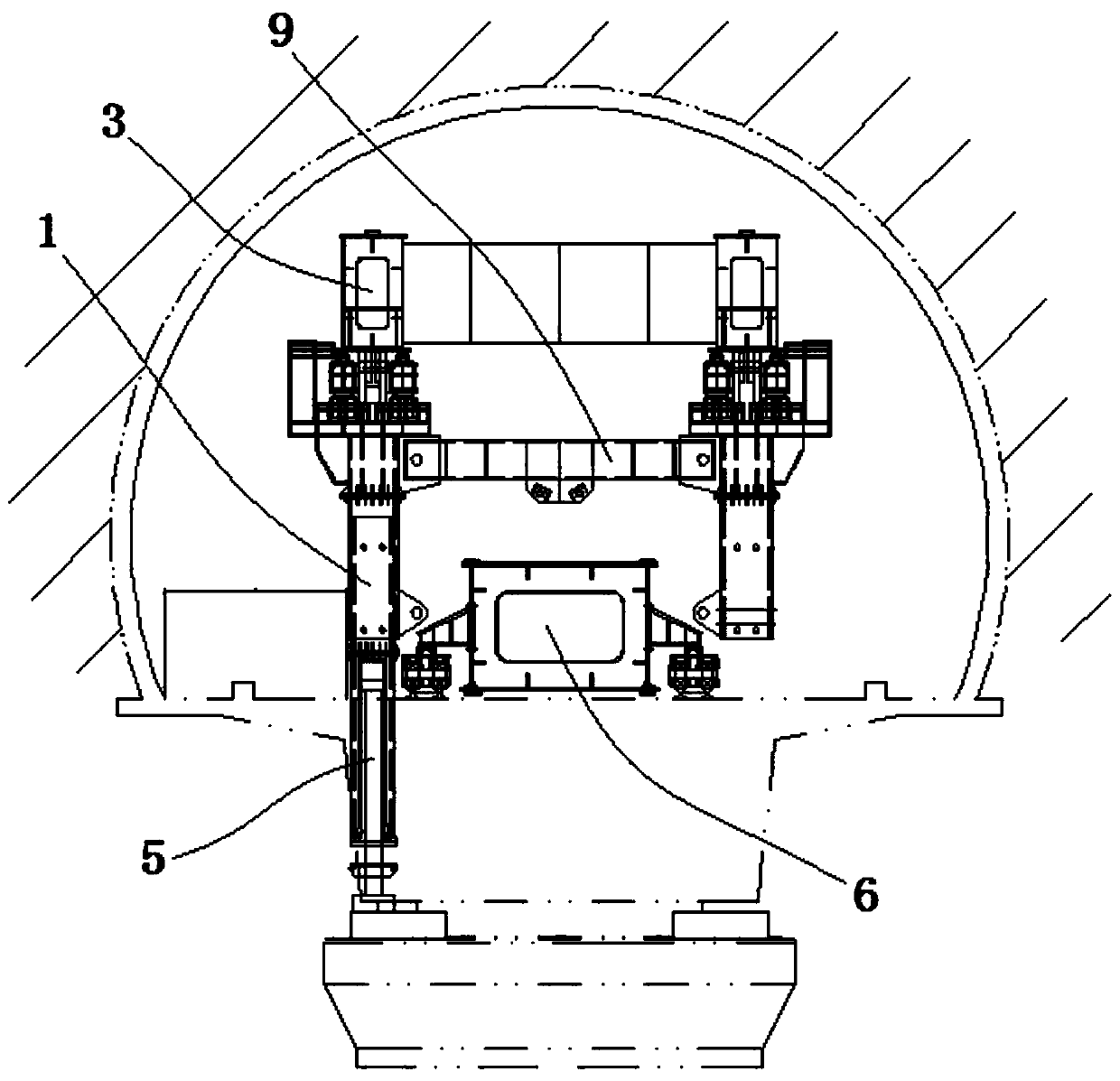
[0004] The purpose of the present invention is to provide a method for the lower guide beam type fixed-point hoisting bridge erecting machine based on the front outrigger to pass through the tunnel. The system conversion is realized by using the oil cylinder support and the pin shaft connection, and the vertical displacement of the HILMAN roller is combined to realize the erection. The position of the girder erection can be changed by the front outrigger of the girder machine, which is easy to operate, and solves the problems of the existing down-guiding girder type fixed-point hoisting bridge erecting machine with complex structure, need to disassemble when passing through the tunnel, heavy removal workload, and complicated operation

Method used


Image

  • The method of the lower guide beam type fixed-point hoisting bridge erecting machine passing through the tunnel based on the front outrigger
  • The method of the lower guide beam type fixed-point hoisting bridge erecting machine passing through the tunnel based on the front outrigger
  • The method of the lower guide beam type fixed-point hoisting bridge erecting machine passing through the tunnel based on the front outrigger

Examples


Embodiment Construction

[0032] The technical solutions in the embodiments of the present invention will be clearly and completely described below in conjunction with the accompanying drawings in the embodiments of the present invention. Obviously, the described embodiments are only a part of the embodiments of the present invention, rather than all the embodiments. Based on the embodiments of the present invention, all other embodiments obtained by those of ordinary skill in the art without creative work shall fall within the protection scope of the present invention.

[0033] In the description of the present invention, it should be understood that the terms "between", "upper", "lower", "anchor", "lifting", "middle", "contact", "turning", "pinning" "," "holding", "upper" and other indicating orientation or positional relationships are only for the convenience of describing the present invention and simplifying the description, rather than indicating or implying that the referred components or elements m...


PUM


Abstract

The invention discloses a lower launching nose type fixed-point hoisting bridge girder erection machine through-tunnel method based on a front support leg, and relates to the technical field of bridgegirder erection machines. The method comprises the following steps: anchoring the lower end of the front support leg with the ground; changing span of the bridge girder erection machine; laying downa roller to make the roller completely contact with a launching nose track; turning over the lower section of the front support leg, and driving, by a rear support leg, the bridge girder erection machine go out of the tunnel; removing a lower cross beam and mounting an upper cross beam to original position; recovering support of the lower section of the front support leg, and enabling an oil cylinder at the upper end of the front support leg to work; jacking the front support leg up to a normal girder erection state. According to the method disclosed by the invention, system transformation isrealized through oil cylinder support and hinge pin connection; in combination with the longitudinal shift of an HILMAN roller, the girder erection position of the front support leg of the bridge girder erection machine is changed; the structural form is simple and the operation is convenient; by integrating the longitudinal shift walking drive of the launching nose and the longitudinal shift walking drive of the bridge girder erection machine, the structural form is simple; when passing through the tunnel, the transporting girder vehicle carries the launching nose and the bridge girder erection machine to pass through the tunnel at one time, thus the discharge workload is small, and the working condition adaptability is relatively good.

Description

Technical field [0001] The invention belongs to the technical field of bridge erecting machines, and particularly relates to a method for a lower guide beam type fixed-point hoisting bridge erecting machine based on front legs to pass through a tunnel. Background technique [0002] The bridge erecting machine is the equipment that puts the prefabricated beams on the prefabricated bridge piers. The bridge erecting machine belongs to the category of cranes, because its main function is to lift the beams, then transport them to the location and then put them down. A bridge construction machine that runs on highways and railway tracks and is used to erect small-span beams across the entire span. Because of its high efficiency in bridge construction, in the standard design of Chinese railway bridges, it is often considered as the design principle. The fuselage is huge, exceeding the railway transportation limit, and must be disassembled and transported, and then assembled and used a...

Claims


Application Information

Patent Timeline
Patent Type & Authority Patents(China)
IPC IPC(8): E01D21/00
CPCE01D21/00
Inventor 袁攀峰
Owner 袁攀峰
Learn More