Rotor system and control method of rotor system as well as gas turbine generator set and control method of gas turbine generator set

A rotor, compressor technology, used in gas turbine installations, machines/engines, mechanical equipment, etc.

Pending Publication Date: 2018-11-23
刘慕华
View PDF5 Cites 13 Cited by
  • Summary
  • Abstract
  • Description
  • Claims
  • Application Information

AI Technical Summary

Problems solved by technology

[0006] The present invention provides a rotor system and its control method, a gas turbine generator set and it

Method used


Image

  • Rotor system and control method of rotor system as well as gas turbine generator set and control method of gas turbine generator set
  • Rotor system and control method of rotor system as well as gas turbine generator set and control method of gas turbine generator set
  • Rotor system and control method of rotor system as well as gas turbine generator set and control method of gas turbine generator set

Examples


Embodiment 1

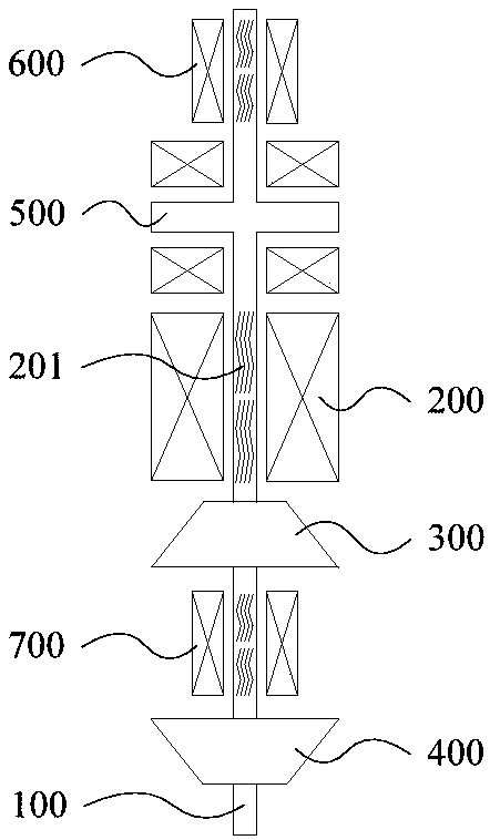
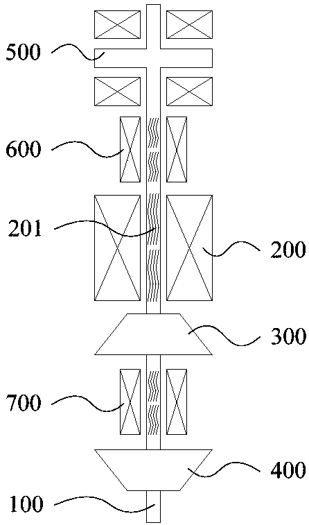
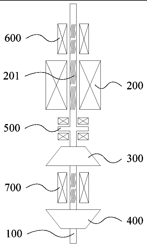
[0193] Such as Figure 1 to Figure 3 As shown, the rotor system includes:

[0194] The rotating shaft 100, the shaft body of the rotating shaft 100 is an integral structure, and the rotating shaft 100 is vertically arranged;

[0195] The motor 200, the compressor 300 and the turbine 400 are sequentially arranged on the rotating shaft 100;

[0196] And, the thrust bearing 500, the first radial bearing 600 and the second radial bearing 700 arranged on the rotating shaft 100, the first radial bearing 600 is arranged on the side of the motor 200 away from the compressor 300, the second radial bearing 700 is provided between the compressor 300 and the turbine 400 .

[0197] The thrust bearing 500 is arranged between the first radial bearing 600 and the motor 200, such as figure 1 shown; or, the thrust bearing 500 is arranged on the side of the first radial bearing 600 away from the motor 200, as figure 2 shown; or, the thrust bearing 500 is arranged between the motor 200 and t...

Embodiment 2

[0211] Such as Figure 7 to Figure 10 As shown, the rotor system includes:

[0212] The rotating shaft 100, the shaft body of the rotating shaft 100 is an integral structure, and the rotating shaft 100 is vertically arranged;

[0213] The motor 200, the compressor 300 and the turbine 400 are sequentially arranged on the rotating shaft 100;

[0214]And, the thrust bearing 500, the first radial bearing 600, the second radial bearing 700 and the third radial bearing 800 arranged on the rotating shaft 100, the first radial bearing 600 is arranged on a side of the motor 200 away from the compressor 300 On the side, the second radial bearing 700 is arranged between the compressor 300 and the turbine 400 , and the third radial bearing 800 is arranged between the motor 200 and the compressor 300 .

[0215] The thrust bearing 500 is arranged between the first radial bearing 600 and the motor 200, such as Figure 7 shown; or, the thrust bearing 500 is arranged on the side of the firs...

Embodiment 3

[0224] Such as Figure 15 As shown, the rotor system includes:

[0225] The rotating shaft 100, the shaft body of the rotating shaft 100 is an integral structure, and the rotating shaft 100 is vertically arranged;

[0226] The motor 200, the compressor 300 and the turbine 400 are sequentially arranged on the rotating shaft 100;

[0227] And, the thrust bearing 500, the first radial bearing 600, the second radial bearing 700 and the fourth radial bearing 900 arranged on the rotating shaft 100, the first radial bearing 600 is arranged on a side of the motor 200 away from the compressor 300 side, the second radial bearing 700 is arranged between the compressor 300 and the turbine 400, the fourth radial bearing 900 is arranged on the side of the turbine 400 away from the compressor 300, and the thrust bearing 500 is arranged between the compressor 300 and the first between the two radial bearings 700 .

[0228] The embodiment of the present invention can be applied to the situa...


PUM


Abstract

The invention provides a rotor system and a control method of the rotor system as well as a gas turbine generator set and a control method of the gas turbine generator set. The rotor system comprisesa rotating shaft, a motor, a gas compressor and a turbine as well as a thrust bearing and at least two radical bearings, wherein a shaft body of the rotating shaft is of an integrated structure, the rotating shaft is vertically arranged, the motor, the gas compressor and the turbine are sequentially arranged on the rotating shaft, the thrust bearing and the radial bearings are arranged on the rotating shaft, the thrust bearing and the radial bearings are non-contact bearings, the thrust bearing is arranged at a preset position of one side, close to the gas compressor, of the turbine, and the preset position is the position where the center of gravity of the rotator system can be located between the two radial bearings which are spaced by the largest distance. According to the rotator system, the non-contact type bearings are adopted so that the rotor system can be vertically arranged; and in this way, the gravity center of the rotator system is located at the axis, static deflection cannot be generated, moreover, the torque generated by the gravity on the axis is zero, therefore, the influence of the gravity on the rotation of the rotator system can be eliminated, and then the stability of the rotator system can be improved.

Description

technical field [0001] The invention relates to the technical field of rotors, in particular to a rotor system and a control method thereof, a gas turbine generator set and a control method thereof. Background technique [0002] A gas turbine mainly includes three major components: a compressor, a combustor, and a turbine. After the air enters the compressor, it is compressed into high-temperature and high-pressure air, and then supplied to the combustion chamber for mixed combustion with fuel, and the high-temperature and high-pressure gas generated expands in the turbine to perform work. When the rotor rotates at high speed, the rotor will be subjected to radial force and axial force. In order to limit the radial and axial movement of the rotating shaft, radial bearings and thrust bearings need to be installed in the rotor system. Traditional radial bearings and thrust bearings generally use contact bearings such as oil film lubricated bearings or rolling bearings. [0...

Claims


Application Information

Patent Timeline
IPC IPC(8): F01D5/02F02C7/06F02C6/00F02C9/00
CPCF01D5/02F02C6/00F02C7/06F02C9/00
Inventor 靳普
Owner 刘慕华
Why Eureka
Try Eureka