Eureka AIR delivers breakthrough ideas for toughest innovation challenges, trusted by R&D personnel around the world.

Centrifugal pump radial sealing ring with cylindrical guide vanes

A technology of guide vanes and radial seals, which is applied to parts, pumps, and pump elements of pumping devices used for elastic fluids, and can solve problems affecting the hydraulic performance of the impeller, unfavorable processing and assembly, and complex processing technology. Improve performance, reduce processing and assembly difficulty, and simplify replacement

Active Publication Date: 2018-11-23
JIANGSU UNIV
View PDF8 Cites 3 Cited by
  • Summary
  • Abstract
  • Description
  • Claims
  • Application Information

AI Technical Summary

Problems solved by technology

At present, there are two commonly used sealing methods between the volute and the impeller: one is to set the leakage gap between the mouth ring and the impeller in a small range; the other is to use a labyrinth seal by setting a complex sealing structure. However, when the gap is set to be small, the wear is serious, and the stability will be poor, and the overly complicated sealing structure is not conducive to processing and assembly
[0003] At present, in order to solve a series of problems such as severe wear and difficult assembly caused by reducing the gap, a non-contact sealing structure that can ensure good sealing performance under a large gap has been proposed.
For example, Chinese patent application number 201420065364.3 proposes a high-efficiency centrifugal pump with impeller with non-contact sealing function. The annular impeller seal ring extending on both sides of the impeller and the pump body built into the pump body match the impeller seal ring. Threads are machined on the inner surface of the wear-resistant ring to reduce or prevent the leakage at the radial gap of the impeller seal ring. Affects the hydraulic performance of the impeller; thread seals wear during use, and once worn excessively, the entire impeller needs to be replaced, which increases maintenance costs

Method used


Image

  • Centrifugal pump radial sealing ring with cylindrical guide vanes
  • Centrifugal pump radial sealing ring with cylindrical guide vanes
  • Centrifugal pump radial sealing ring with cylindrical guide vanes

Examples


Embodiment Construction

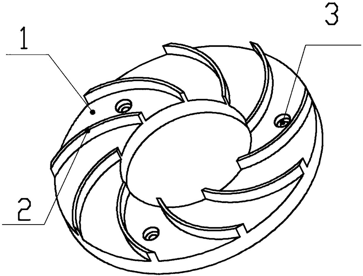
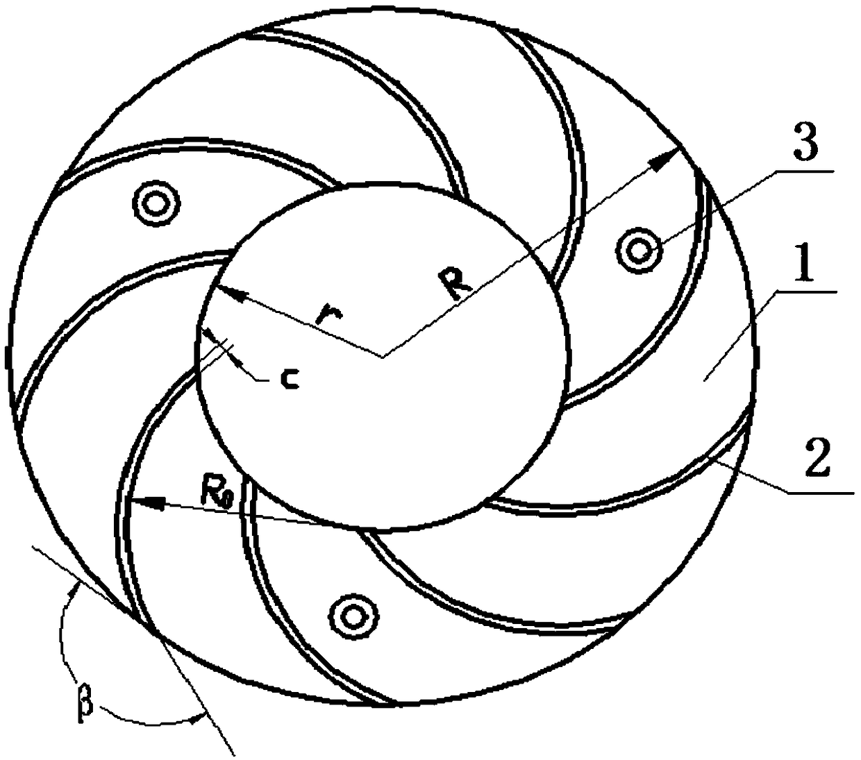
[0020] see Figure 1-2 As shown, the present invention is made up of disc 1 and radial guide vane 2, and the middle of disc 1 has a central through hole. A plurality of radial guide vanes 2 are evenly and fixedly arranged along the circumferential direction on one side of the disc 1 , and the radial guide vanes 2 protrude axially from the disc surface of the disc 1 . Each radial guide vane 2 is a cylindrical plate, and the central axis of the cylindrical plate is perpendicular to the disc surface of the disc 1 . Several countersunk screw holes 3 are processed on the surface of the disc 1 for fixing the disc 1 .

[0021] see Figure 4 and Figure 5 , the present invention is installed between the volute 4 and the impeller 5 of the centrifugal pump. When installing, the central axis of the disc 1 is required to be in line with the central axis of the impeller 5. Fixedly connected to the volute 4, the radial guide vane 2 faces the impeller 5, and the radial guide vane 2 and t...


PUM


Abstract

The invention discloses a centrifugal pump radial sealing ring which is provided with cylindrical guide vanes and mounted at a gap between a volute and an impeller. The centrifugal pump radial sealingring is composed of a disc and the radial guide vanes. The multiple radial guide vanes are evenly arranged on the disc surface of one side of the disc in the circumferential direction. Each radial guide vane is a cylindrical plate. The central axis of each cylindrical plate is perpendicular to the disk surface of the disc. The contour of the radial cross section of each radial guide vane is an arc with any point on an inner ring contour as the circle center and with the radius being R0. The starting point of each arc is located on the inner ring contour of the disc, and the end point of eacharc is located on an outer ring contour of the disc. The centrifugal pump radial sealing ring is a non-contact sealing ring. When a centrifugal pump impeller rotates, rotating liquid generates directional flow under induction of the fixed radial guide vanes, the induction direction is opposite to the moving direction of leakage fluid between the impeller and the volute, and thus the purpose of preventing fluid from leaking from the gap between the impeller and the volute is achieved.

Description

technical field [0001] The invention relates to a centrifugal pump structure in the field of fluid machinery, in particular to a centrifugal pump sealing device installed in the gap between the volute and the impeller to prevent fluid leakage between the volute and the impeller. Background technique [0002] A centrifugal pump is a typical blade-type fluid machine. Its working principle is to drive the impeller to rotate through the prime mover to do work on the fluid, and convert the mechanical energy into the kinetic energy and pressure energy of the fluid, so as to realize the transportation of the fluid. The work process of the impeller of the centrifugal pump is inevitably accompanied by energy loss. The energy loss is mainly divided into three types: flow loss, volume loss and disc friction loss. Among them, the volume loss refers to the flow loss caused by the leakage between the impeller rotation and the casing. The leakage is related to the pressure difference actin...

Claims


Application Information

Patent Timeline
Patent Type & Authority Applications(China)
IPC IPC(8): F04D29/16F04D29/44
CPCF04D29/167F04D29/448
Inventor 何秀华卞荣群邓志丹
Owner JIANGSU UNIV
Why Eureka
Eureka Blog
Learn More