an oil inlet valve

An oil inlet valve and oil inlet technology, applied in the field of hydraulic valves, can solve problems such as troublesome shunt structure, and achieve the effect of stable pressure and flow

Active Publication Date: 2020-06-26
SHANGHAI KAIGONG VALVE CO LTD
View PDF7 Cites 0 Cited by
  • Summary
  • Abstract
  • Description
  • Claims
  • Application Information

AI Technical Summary

Problems solved by technology

[0005] In the shunting system in the prior art, the shunting structure is relatively troublesome, and the shunting is carried out smoothly

Method used


Image

  • an oil inlet valve
  • an oil inlet valve
  • an oil inlet valve

Examples


Embodiment

[0035] An embodiment, a working method of an oil inlet valve plate, comprising the following steps:

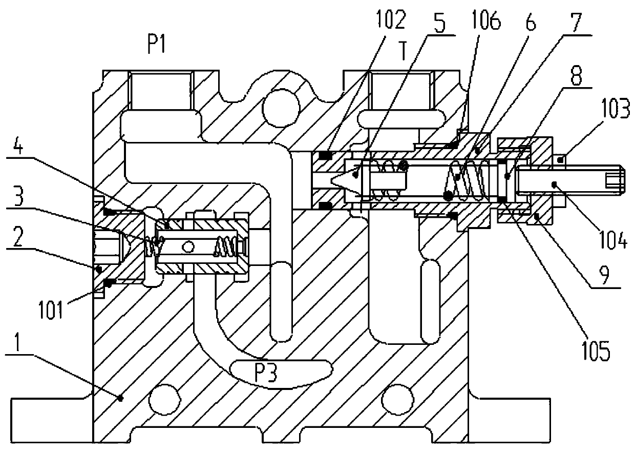
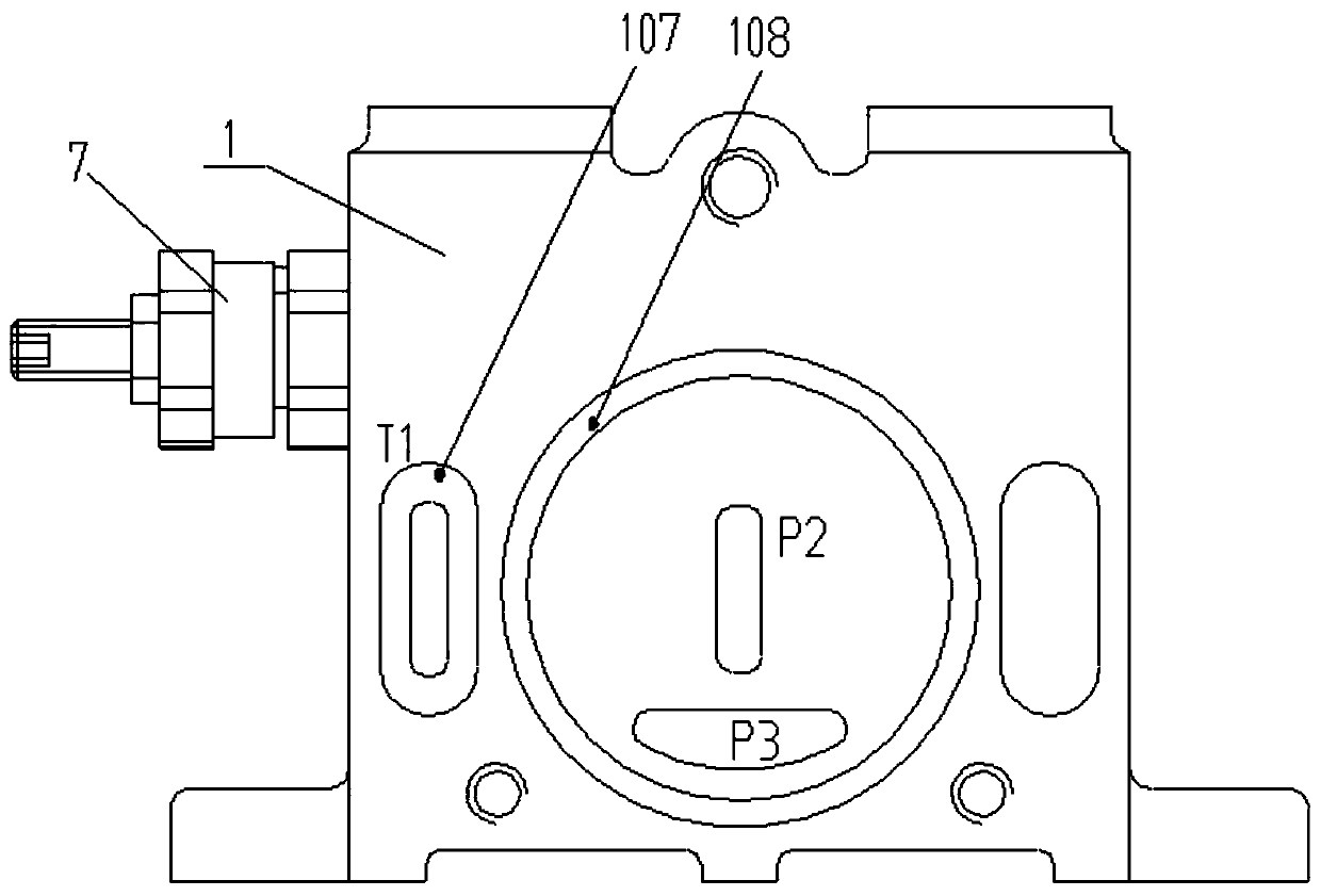
[0036] Step 1: After connecting the device with the outside, connect the oil pump to the oil inlet P1, and the oil inlet P1 is diverted to the oil inlet P2 through the oil passage inside the valve body 1, and the other way is diverted to the oil inlet P2 through the diverter valve core 4. Oil inlet P3;

[0037] Step 2: When the pressure oil in the oil inlet P1 is greater than the elastic force of the spring 6, the pressure oil overcomes the elastic force of the spring 6 and pushes the valve needle 5 to the right, and the pressure oil flows into the oil return port T through the oil hole 701;

[0038] Step 3: After the pressure oil and the oil return port T are connected, the pressure drops, the spring force of the spring 6 is greater than the force of the pressure oil acting on the valve needle 5, and the spring 6 resets to push the valve needle 5 to the left, closing the oil in...


PUM


Abstract

The invention discloses an oil inlet valve plate. The oil inlet valve plate comprises a valve body, a plug head and a flow distribution valve element, wherein an air inlet port P1 is formed in the left side of the valve body; an oil return port T is formed in the right side of the valve body; an oil inlet port P2 and an oil inlet port P3 are formed in the front surface of the valve body; the air inlet port P1 is connected with the oil inlet port P2 through an oil channel in the valve body; the air inlet port P1 is connected with the oil inlet port P3 through an oil channel in the valve body; the flow distribution valve element is arranged on an oil path between the air inlet port P1 and the oil inlet port P3; one end away from the flow distribution valve element, of a flow distribution spring, is abutted against the plug head; an oil return hole T1 is further formed in the front surface of the valve body; a safety valve sleeve is arranged between the air inlet port P1 and the oil return port T; the safety valve sleeve is connected to the right end in the valve body through a thread; a valve needle is arranged in the safety valve sleeve; a spring sleeves one end of the valve needle;the spring and a spring seat are arranged in the safety valve sleeve; and a locking nut is connected outside the other end of a speed adjustment valve element through a thread. The oil inlet valve plate has the characteristic of being stable in pressure and flow rate.

Description

technical field [0001] The invention relates to the related technical field of hydraulic valves, in particular to an oil inlet valve plate. Background technique [0002] The hydraulic valve is an automatic component operated by pressure oil. It is controlled by the pressure oil of the pressure distribution valve. It is usually used in combination with the electromagnetic pressure distribution valve. It can be used to remotely control the on-off of the oil, gas and water pipeline system of the hydropower station. Commonly used in clamping, control, lubrication and other oil circuits. There are direct-acting and pilot-operated types, and the pilot-operated type is mostly used. [0003] Components used in hydraulic transmission to control fluid pressure, flow and direction. Among them, the one that controls pressure is called pressure control valve, the one that controls flow is called flow control valve, and the one that controls on-off and flow direction is called direction...

Claims


Application Information

Patent Timeline
Patent Type & Authority Patents(China)
IPC IPC(8): F15B13/02
CPCF15B13/02F15B13/024F15B2013/002
Inventor 唐万刚
Owner SHANGHAI KAIGONG VALVE CO LTD
Why Eureka
Try Eureka