Low-viscosity liquid ring thickened oil conveying and stabilizing device
A technology for transporting stable and viscous fluids, applied in gas/liquid distribution and storage, pipeline systems, mechanical equipment, etc., can solve problems such as complex structures, difficult-to-seal connections, and density differences, so as to avoid direct contact, reduce transport resistance, reduce The effect of flow obstruction
- Summary
- Abstract
- Description
- Claims
- Application Information
AI Technical Summary
Problems solved by technology
Method used
Image

Examples
Embodiment Construction
[0023] The present invention will be further described below in conjunction with the examples and drawings, but the embodiments of the present invention are not limited thereto.
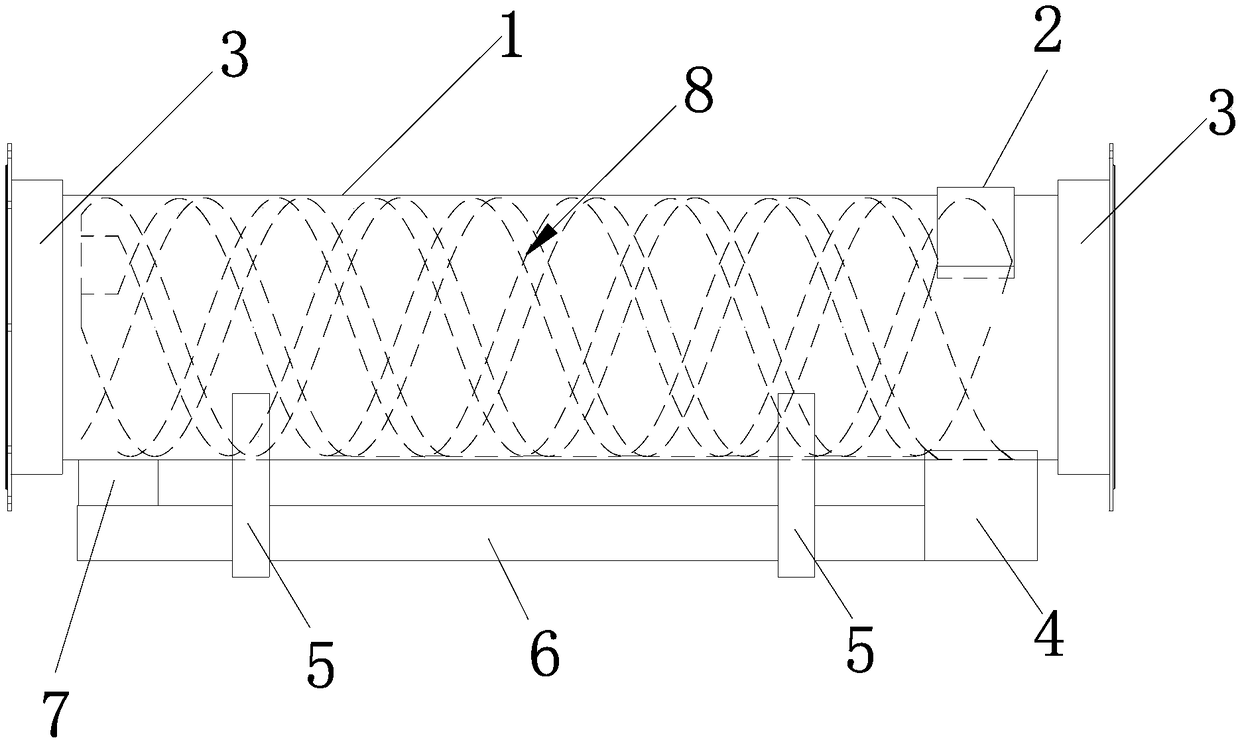
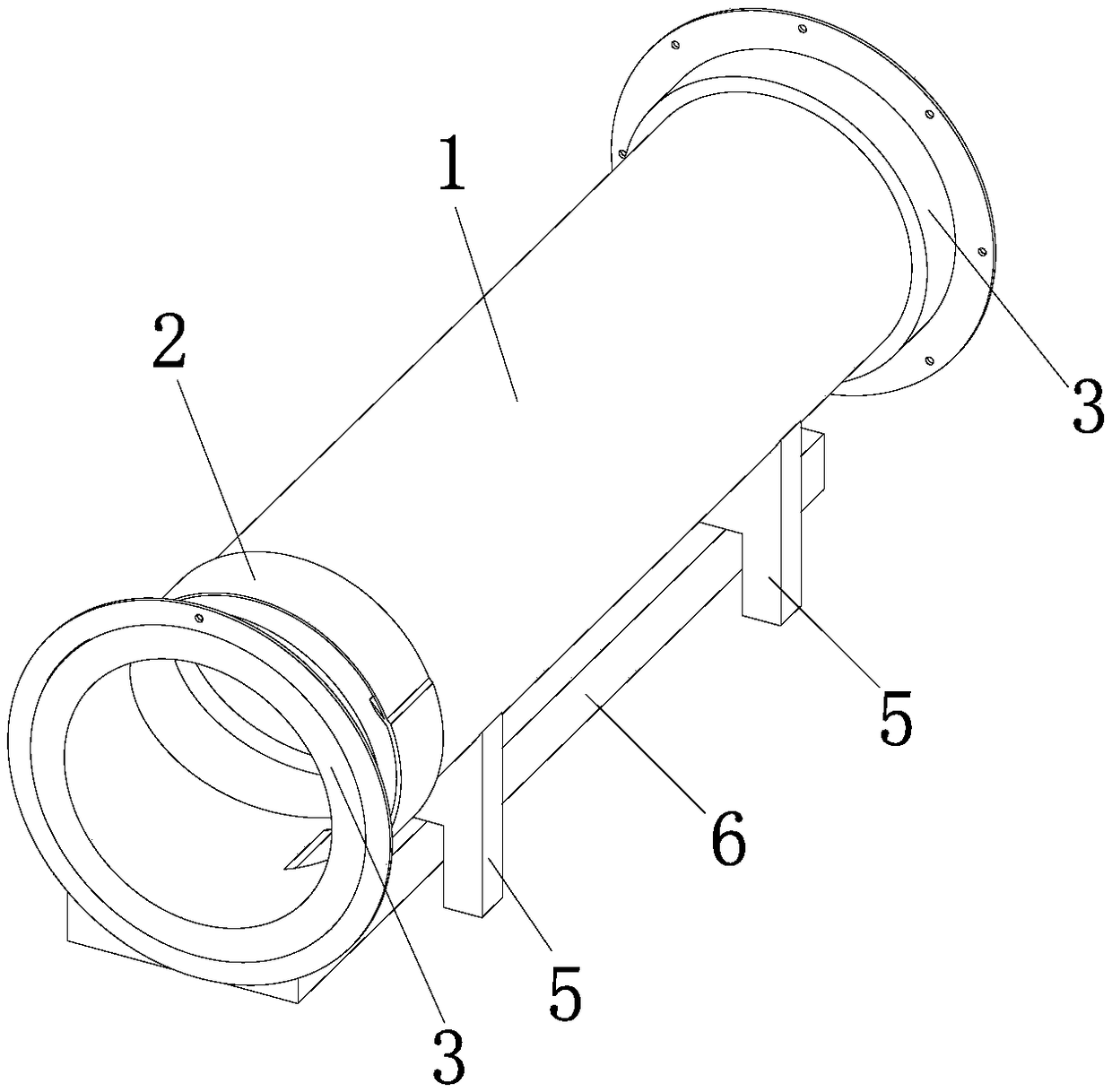
[0024] see Figure 1-Figure 3 , the low-viscosity ring heavy oil transportation stabilization device of this embodiment includes a pipe body 1, a delivery pump 4, a liquid storage tank 6 and a connecting pipe 2; wherein, the inner wall of the pipe body 1 is provided with a spiral groove 8, and the spiral groove The groove 8 extends from the beginning of the pipe body 1 to the end of the pipe body 1 along the axial direction; the inlet of the delivery pump 4 is connected to the liquid storage tank 6, and the liquid storage tank 6 is filled with low-viscosity liquid; One end of the connecting pipe 2 is connected to the outlet of the delivery pump 4 , and the other end passes through the pipe body 1 and is connected to the beginning of the spiral groove 8 .
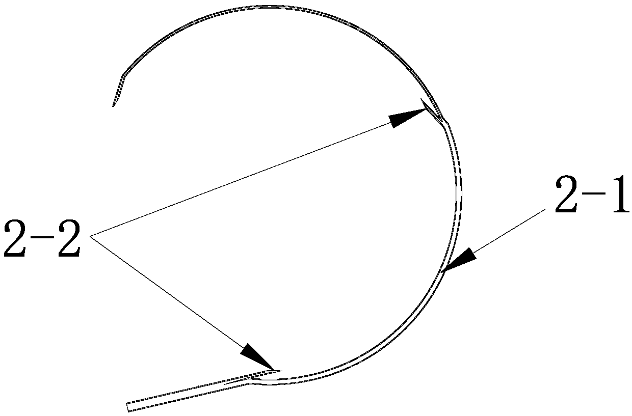
[0025] see Figure 1-Figure 3 , the connec...
PUM
 Abstract
Description
Claims
Application Information
 - Generate Ideas
- Intellectual Property
- Life Sciences
- Materials
- Tech Scout
- Unparalleled Data Quality
- Higher Quality Content
- 60% Fewer Hallucinations
Browse by: Latest US Patents, China's latest patents, Technical Efficacy Thesaurus, Application Domain, Technology Topic, Popular Technical Reports.
© 2025 PatSnap. All rights reserved.Legal|Privacy policy|Modern Slavery Act Transparency Statement|Sitemap|About US| Contact US: help@patsnap.com