Radiation refrigeration particle and steam condensation recycling device

A radiation refrigeration and recovery device technology, applied in refrigeration and liquefaction, steam/vapor condensers, refrigerators, etc., can solve the problems of high adsorbent efficiency requirements, large power consumption, human and environmental harm to adsorbents, etc. Heat transfer performance, promotion of vapor condensation, and good condensation efficiency

Active Publication Date: 2018-11-23
ZHEJIANG UNIV
View PDF10 Cites 0 Cited by
  • Summary
  • Abstract
  • Description
  • Claims
  • Application Information

AI Technical Summary

Problems solved by technology

[0005] The electric condensation method needs to consume a large amount of electric energy to take away the heat of the steam, while the

Method used


Image

  • Radiation refrigeration particle and steam condensation recycling device
  • Radiation refrigeration particle and steam condensation recycling device
  • Radiation refrigeration particle and steam condensation recycling device

Examples


Example Embodiment

[0044] Implementation mode one

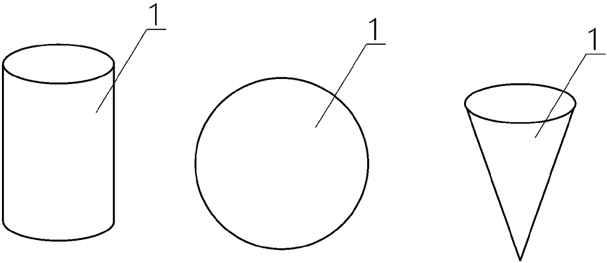
[0045] The first embodiment of the present invention provides a radiant refrigeration particle 1, see figure 1 As shown, at least part of the radiant refrigeration particles 1 are made of radiant refrigeration materials, and are suspended in the medium during use to condense the vapor in the medium.

[0046] Among them, the radiant refrigeration material is a material that can use infrared radiation to transfer the heat of the heat source through the atmospheric window of infrared radiation to the outer space cold source. The cooling principle is similar to the natural cooling principle of the earth.

[0047] Those of ordinary skill in the art know that the 200 petawatts of energy the earth absorbs from the sun every day is ultimately transported to the space close to absolute zero in a radiant manner, so that its own temperature can be balanced within a certain range.

[0048] The radiant refrigeration material can radiate energy in the form of infrar...

Example Embodiment

[0054] Implementation mode two

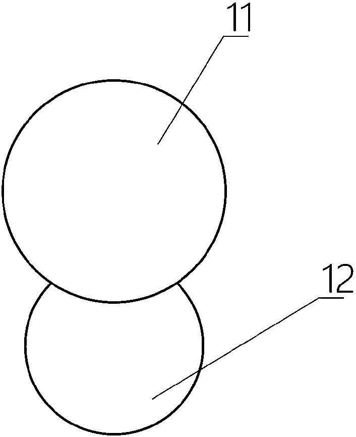
[0055] The second embodiment of the present invention provides a radiant refrigeration particle 1. The second embodiment is a further improvement of the first embodiment. The main improvement lies in that in the second embodiment of the present invention, see figure 2 As shown, the radiant cooling particles 1 include:

[0056] Condensed liquid 11, made of radiant refrigeration material;

[0057] The hydrophobic liquid 12 is connected with the condensed liquid 11 and is made of liquid hydrophobic material;

[0058] The average density of the hydrophobic liquid 12 is greater than the average density of the condensed liquid 11.

[0059] Among them, see figure 2 As shown, the shape of the condensed liquid 11 is not particularly limited, and a spherical shape exhibiting the largest surface area is preferred. The shape of the phobic liquid 12 can be a spherical shape that is easier to process.

[0060] According to the type of medium, the material of the hy...

Example Embodiment

[0062] Implementation mode three

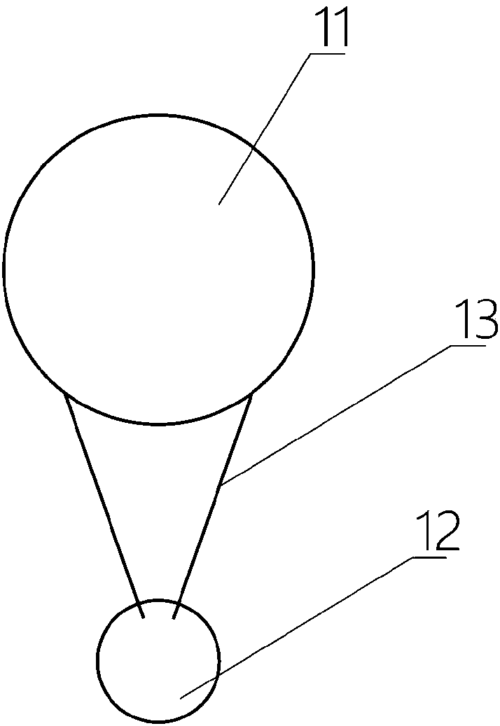
[0063] The third embodiment of the present invention provides a radiant refrigeration particle 1. The third embodiment is a further improvement of the second embodiment, the main improvement lies in the third embodiment of the present invention, see image 3 As shown, further, in this embodiment, the phobic liquid 12 is connected to the condensed liquid 11 through a wire 13.

[0064] The condensed liquid 11 and the hydrophobic liquid 12 are connected by a wire 13, compared to the direct connection between the two, which can make the surface area exposed by the condensed liquid 11 and the hydrophobic liquid 12 larger. The droplets formed on the condensed liquid 11 can flow along the thread 13 to the phobic liquid 12, which is more conducive to the collection of the condensed liquid.

[0065] In addition, the flexible connection of the wire 13 can also better ensure that the relative position of the phobic liquid 12 is always below the condensed liqu...


PUM


Abstract

The invention relates to the field of steam recycling, and discloses a radiation refrigeration particle and a steam condensation recycling device. At least part of the radiation refrigeration particleis made from a radiation refrigeration material. During use, the radiation refrigeration particle suspends in a medium, and is used for condensing steam in the medium. The steam condensation recycling device comprises a steam condensation cavity and the radiation refrigeration particle. The steam condensation cavity is full of the medium, and the radiation refrigeration particle suspends in the medium and is used for condensing the steam in the medium. According to the radiation refrigeration particle and the steam condensation recycling device, latent heat of condensation can be fast released to the external environment through radiation heat exchange without additional energy input or adsorbent, and the steam is efficiently condensed.

Description

technical field [0001] The invention relates to the field of steam recovery, in particular to a radiation refrigeration particle and steam condensation recovery device. Background technique [0002] Most of my country's new coal-fired units are built in the western coal-producing areas, and these areas are water-scarce areas. How to build large-scale coal power bases in water-scarce areas is a thorny issue for energy workers. After actively installing air-cooled condensers in newly-built units of coal-fired power plants in my country's water-scarce areas, the water consumption of the power plants has been greatly reduced. However, the steam emitted by a 600MW unit through the chimney is about 300t / h, and the annual water discharge is about 1.5 million tons. The water consumption is still very alarming. If the water in the chimney can be recovered and utilized as a resource, it will strongly support the construction of my country's coal power base, and it will be of great si...

Claims


Application Information

Patent Timeline
IPC IPC(8): F25B23/00F28B9/08
CPCF25B23/003F28B9/08
Inventor 肖刚赖华盛倪明江骆仲泱高翔程乐鸣岑可法
Owner ZHEJIANG UNIV
Why Eureka
Try Eureka