Method and system for measuring generator voltage adjustment ratio

A technology of generator voltage and droop rate, applied in the field of power system

Active Publication Date: 2018-11-23
CHINA ELECTRIC POWER RES INST
View PDF13 Cites 6 Cited by
  • Summary
  • Abstract
  • Description
  • Claims
  • Application Information

AI Technical Summary

Problems solved by technology

[0005] The present invention proposes a method and system for measuring the generator voltage differential rate to solve the problem of how to accurately measure the generator voltage differential rate

Method used


Image

  • Method and system for measuring generator voltage adjustment ratio
  • Method and system for measuring generator voltage adjustment ratio
  • Method and system for measuring generator voltage adjustment ratio

Examples


Embodiment approach

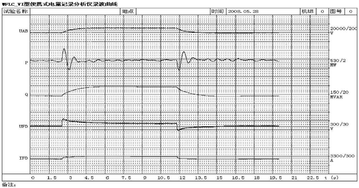
[0074] by figure 2 The test result of a 600MW thermal power unit shown as an example further illustrates the present invention in detail, but the present invention is not limited to the given example. figure 2 It is the recorded wave diagram of the ±2% step response test without PSS according to the recorded wave result of the actual test according to the embodiment of the present invention. like figure 2 As shown, UAB and Q are the response curves of generator stator voltage U(t) and reactive power Q(t), respectively. Among them, the generator voltage step start time is 1.8s, the generator voltage step end time is 10.9s, the steady state point generator stator voltage and reactive power before the step can be read within 0s-1.8s, 1.8 The steady-state point generator stator voltage and reactive power after the step can be read within s-10.9s.

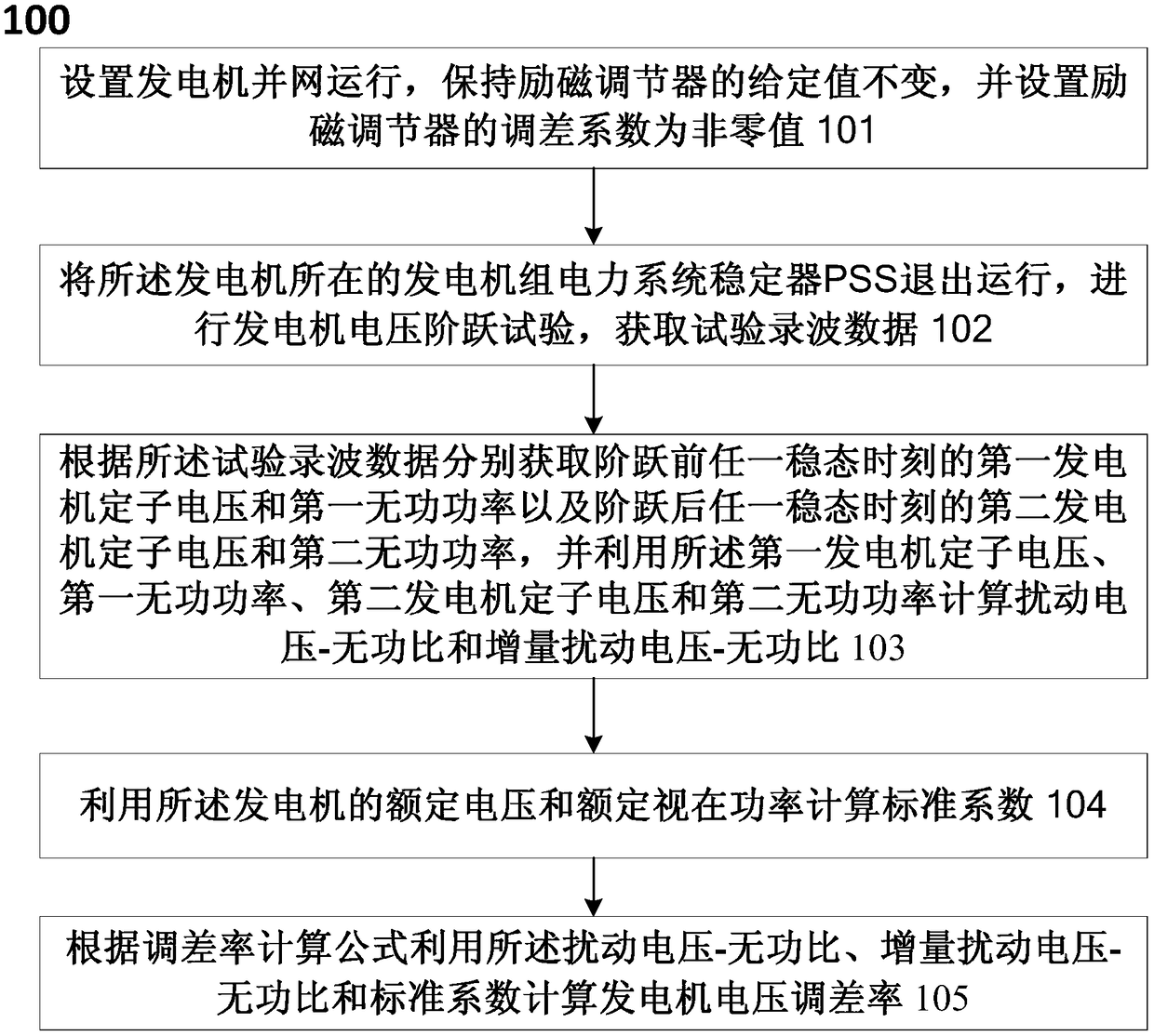
[0075] The steps of measuring the generator voltage droop rate according to the embodiment of the present invention are as follo...


PUM


Abstract

The invention relates to a method for measuring generator voltage adjustment ratio. The method comprises the following steps: grid-connected operation of the generator is set, the set value of an excitation adjuster is kept unchanged and the difference adjustment coefficient of the excitation adjuster is set to be a non-zero value; the power system stabilizer PSS of the generator set in which thegenerator is located is withdrawn from operation, the voltage step test of the generator is performed and the test recording data are obtained; the first generator stator voltage and the first reactive power at any steady state moment before the step and the second generator stator voltage and the second reactive power at any steady state moment after the step are obtained according to the test recording data, and the disturbance voltage-reactive power ratio and the incremental disturbance voltage-reactive power ratio are calculated; the standard coefficient is calculated by using the rated voltage and the rated apparent power of the generator; and the voltage adjustment ratio of the generator is calculated according to the adjustment ratio calculation formula. Onsite measurement of the generator voltage adjustment ratio is realized and a solution for convenient and accurate onsite measurement of the generator voltage adjustment ratio is provided.

Description

technical field [0001] The present invention relates to the technical field of power systems, and more particularly, to a method and a system for measuring the voltage droop rate of a generator. Background technique [0002] With the development of large-scale interconnected power systems, the safe and stable operation of the power system has become increasingly important. Now, in larger power plants, several generator-transformer units are running in parallel under the same bus. Changing the excitation current of any one unit will not only affect the The reactive current of the unit, but also affects the reactive current of other parallel running units, thus causing the change of the bus voltage. In order to prevent the disordered distribution of reactive power among the units, the excitation regulator has introduced the function of additional voltage difference adjustment. The additional voltage difference adjustment function of the generator can ensure the reasonable dist...

Claims


Application Information

Patent Timeline
Patent Type & Authority Applications(China)
IPC IPC(8): G01R31/34
CPCG01R31/343
Inventor 高磊霍承祥褚晓杰夏潮吴剑超朱艳卿何凤军卜广全汤涌
Owner CHINA ELECTRIC POWER RES INST
Why Eureka
Try Eureka