A Fluxgate Magnetic Sensor with a Magnetic Core Skeleton Structure
A skeleton structure and magnetic sensor technology, applied in the field of sensors, can solve problems affecting the accuracy of fluxgate magnetometers and poor feedback effects, and achieve the effects of convenient mass production, easy installation, and consistent thermal expansion coefficients
Active Publication Date: 2020-07-24
INST OF GEOLOGY & GEOPHYSICS CHINESE ACAD OF SCI +1
View PDF12 Cites 0 Cited by
- Summary
- Abstract
- Description
- Claims
- Application Information
AI Technical Summary
Problems solved by technology
The feedback effect is poor, affecting the accuracy of the fluxgate magnetometer
Method used
View moreImage
Smart ImageViewing Examples
Examples
Embodiment approach
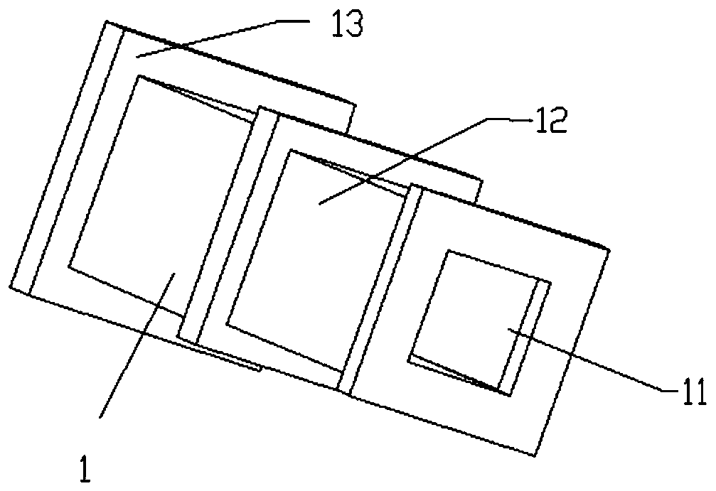
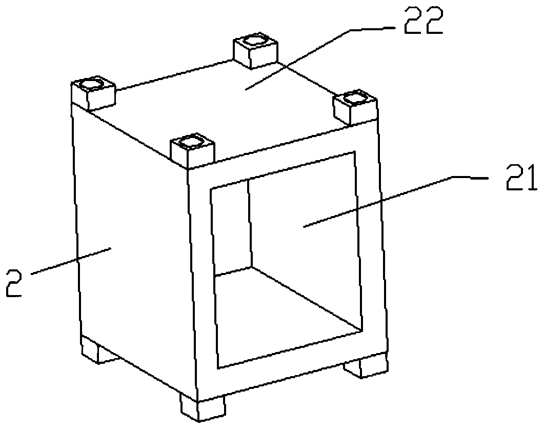
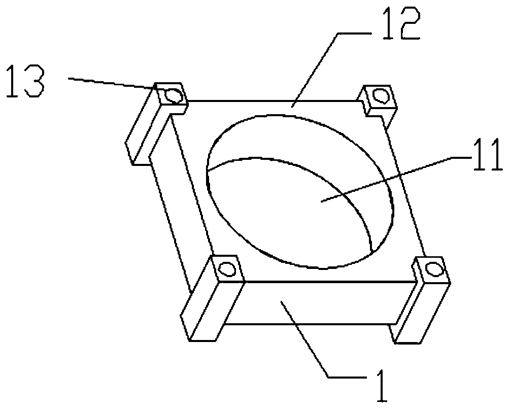
[0035] As a preferred embodiment of the present invention, the induction coil support frame is a sleeve structure, and the size of the induction coil support frame is adjusted according to the size of the magnetic core.
Login to View More PUM
 Abstract
The invention belongs to the technical field of sensors and concretely relates to a flux gate magnetic sensor with a novel magnetic core skeleton structure. An inner frame and an outer frame are adopted to cooperate with each other, a magnetic core wound by an excitation coil is arranged in a first chamber in the inner frame, an induction coil is wound around the inner frame, and a feedback coil is wound around the outer frame, so uniformity of a feedback field can be ensured. Moreover, the cooperation between the inner and outer frames enables installation to be easier, the later calibrationwork to be easier, and facilitates batch production. Meanwhile, the frames made from PEEK, which is lighter, cheaper and easier to process compared with materials of a conventional sensor, and the frames also has the advantages of electrical insulation, high temperature resistance, light weight, high tensile strength, basic consistence between thermal expansion coefficients and enameled wires, etc.
Description
technical field [0001] The invention belongs to the technical field of sensors, in particular to a fluxgate magnetic sensor with a magnetic core skeleton structure. Background technique [0002] Research on fluxgate sensors has focused on three geometries: rod, racetrack, and ring. Among these geometries, the rod has poorer sensitivity and higher noise level due to its open end near the via bend. On the other hand, with a large demagnetization factor for the axis perpendicular to the rod length, this geometry responds well to crossed magnetic fields. The closed-loop geometry of the racetrack-shaped sensor is advantageous, the noise of the magnetization is kept to a minimum, but the cross-field effect is lower than that of a rod-shaped sensor, and the noise level will be high due to the large mechanical stress applied on the strip towards the turning point of the track. The toroidal core can satisfy i) zero crossing field effect; ii) zero offset value; iii) large dynamic ra...
Claims
Login to View More Application Information
Patent Timeline
 Patent Type & Authority Patents(China)
IPC IPC(8): G01R33/04
CPCG01R33/04
Inventor 唐衡李智李翠红袁恺鑫杜爱民张莹
Owner INST OF GEOLOGY & GEOPHYSICS CHINESE ACAD OF SCI
Features
- R&D
- Intellectual Property
- Life Sciences
- Materials
- Tech Scout
- Unparalleled Data Quality
- Higher Quality Content
- 60% Fewer Hallucinations
Learn More Browse by: Latest US Patents, China's latest patents, Technical Efficacy Thesaurus, Application Domain, Technology Topic, Popular Technical Reports.
© 2025 PatSnap. All rights reserved.Legal|Privacy policy|Modern Slavery Act Transparency Statement|Sitemap|About US| Contact US: help@patsnap.com


