
Isolation switch

A technology of isolating switch and switchgear, which is applied in the direction of electric switch, air switch parts, high-voltage air circuit breaker, etc., can solve the problems of increasing the distance between charged bodies, large insulation distance, and old-fashioned structure, so as to improve safety and reliability. Effect of shortening insulation distance and simplifying assembly process

Pending Publication Date: 2018-11-23
QINGDAO TGOOD ELECTRIC
View PDF6 Cites 1 Cited by
  • Summary
  • Abstract
  • Description
  • Claims
  • Application Information

AI Technical Summary

Problems solved by technology

[0003] (1) The volume is large, the structure is old-fashioned, and most of them use integrated switches, resulting in a large overall volume of the switchgear using the disconnector, which restricts the development of the miniaturization of the switchgear
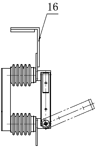
[0004] (2) Defects in the design of the static contact seat: the current structure of the isolating switch is as follows: figure 1 As shown, the insulator is fixed on the support frame of the isolation switch, the contact surface of the moving knife is perpendicular to the lap surface of the busbar, and the connection between the main busbar and the static knife needs to increase the branch busbar (16), the upper and lower two sets of contact surfaces, and the static knife is fixed on the supporting insulator On, the insulator is connected to the bracket
The structure is old-fashioned and complicated, it is difficult to realize the separation of switchgear compartments, the protection level cannot be provided, there are many sharp corners and burrs, and a large insulation distance must be ensured
During the closing process, the moving knife and the static contact seat rigidly impact without buffering, which affects the mechanical life of the product; at the same time, the installation flexibility is limited
[0005] (3) Defects in the design of the movable contact knife: The disconnector generally includes a rotatable movable contact knife. The movable contact knife is generally composed of two or more pieces, one side of which is hinged to the inner conductor of the lower insulating bottom plate, and the other side is a free end. Through the action of the operating mechanism, the free end can be rotated and connected to the static contact and the grounding contact respectively to realize the closing and grounding of the circuit
The existing movable contact knife assembly adopts the bolts that pass through, and the spring is sandwiched in the middle to realize the assembly. This form increases the complexity of the assembly, increases the distance between the charged body, increases the phase spacing, and is affected by the machining accuracy of the fasteners. It is easy to produce tip discharge; the contact pressure needs to be adjusted many times during the debugging process, and the nut has a large error

Method used


Image

  • Isolation switch
  • Isolation switch
  • Isolation switch

Examples


Embodiment 1

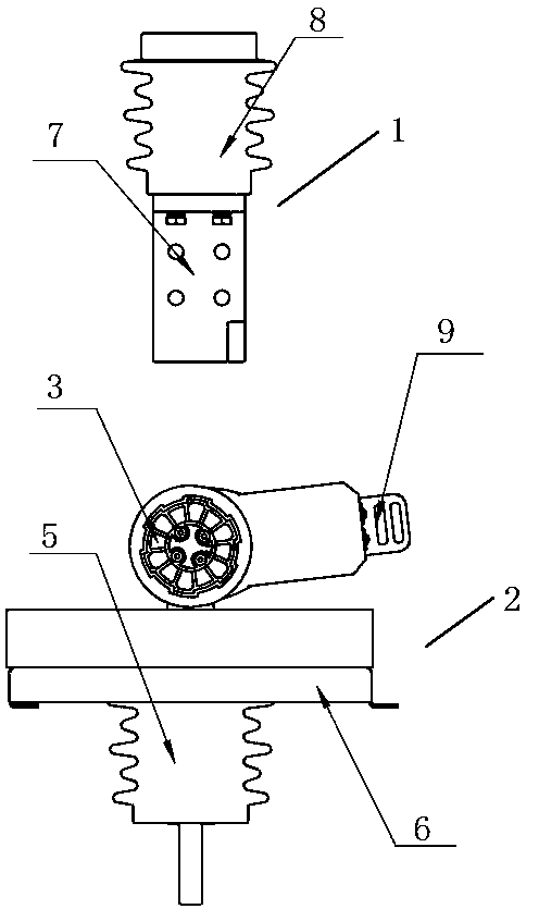
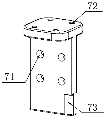
[0034] Such as figure 2 and 4 As shown, the isolating switch includes a static contact seat 1 and a disconnecting switch body 2, the static contact seat 1 and the isolating switch body 2 are separately arranged, the static contact seat 1 is installed inside the switchgear 10, and the isolating switch body 2 is installed in the static contact seat 1 lower part. The static contact seat 1 includes a T-shaped static contact piece 7 and a supporting insulator 8. The upper side of the static contact piece 7 is fixed on the supporting insulator 8, and the lower side is opened or closed with the isolating switch body 2. When closing, the static contact The sheet 7 is overlapped with the disconnector body 2 on the same straight line.

[0035] figure 2 and 4 , combine Figure 5 As shown, the isolating switch body 2 includes a moving contact piece assembly 9, an insulating segmented shaft 3, a conductor 4, an insulating bracket 5 and a supporting frame 6, the insulating bracket 5 ...

Embodiment 2

[0041] This embodiment is illustrated by taking three sets of static contact seats and a disconnector body as examples, and there are three sets of insulated segmented shafts. The structures of the single static contact seat and the main body of the isolating switch are the same as those in Embodiment 1, and will not be repeated here. Just explain the assembly relationship between each group of isolating switch bodies.

[0042] Such as Figure 9-10 As shown, after the assembly of the insulating segmented shaft 3, it is set on the outside of the movable contact piece assembly 9, coaxial with the rotating shaft pin 14 (same as described in Embodiment 1), and the insulating segmented shaft 3 is passed between each group of isolating switch bodies 2. The connection is an integral structure, and the outer ends of the insulating segmented shaft 3 are respectively provided with a left end 31 and a right end 32, and the left end 31 and the right end 32 are connected with the rotating...


PUM


Abstract

The invention discloses an isolation switch. The isolation switch comprises a static contact seat and an isolation switch body, wherein the static contact seat and the isolation switch body are arranged in a split way, and the isolation switch is flexible to assemble and is free from limitation of application equipment. The static contact seat is arranged in switch equipment, the isolation switchbody is arranged at a lower part of the static contact seat, the static contact seat comprises a T-type structure static contact piece and a support insulator, an upper side of the static contact piece is fixed on the support insulator, a lower side of the static contact piece is disconnected or connected with the isolation switch body, and the isolation switch body comprises a static contact piece assembly, a conductor, an insulation support and a support framework. The structure is simplified by the movable contact piece assembly, a traditional penetrating bolt fastening piece is eliminated,an upper group of pull spring and a lower group of pull spring are arranged, the charged body range is reduced, the insulation distance is shortened, the point discharging is reduced, the safety andthe reliability are improved, the assembly process is simplified, the contact pressure can be directly achieved by the upper group of pull spring and the lower group of pull spring, and the debuggingprocess is simplified.

Description

technical field [0001] The invention belongs to the technical field of switchgear for power transmission and distribution, in particular to an isolating switch. Background technique [0002] The main purpose of the isolating switch is to provide a visible fracture during the maintenance process to ensure safety and reliability. It is the most widely used electrical product in high-voltage switching appliances, and its structure is simple. However, there are many defects in the current isolating switches: [0003] (1) The volume is large, the structure is old-fashioned, and most of them use integrated switches, which leads to the overall large volume of the switchgear using the disconnector, which restricts the development of the miniaturization of the switchgear. [0004] (2) Defects in the design of the static contact seat: the current structure of the isolating switch is as follows: figure 1 As shown, the insulator is fixed on the support frame of the isolation switch, t...

Claims


Application Information

Patent Timeline
Patent Type & Authority Applications(China)
IPC IPC(8): H01H31/02
CPCH01H31/023H01H31/026
Inventor 周君许金亮骆祥华
Owner QINGDAO TGOOD ELECTRIC
Learn More