Reactive power compensation and voltage adjustment device for distribution network

A voltage adjustment and distribution network technology, applied in reactive power compensation, substation/distribution device shell, circuit device, etc., can solve the problems of potential safety hazards of connecting wires, no data analysis and processing, easy to damage the inner structure of the wire sheath, etc. , to achieve accurate and efficient judgment and execution of work, and to improve efficiency and accuracy

Inactive Publication Date: 2018-11-23
杭州新融方科技有限公司
View PDF0 Cites 2 Cited by
  • Summary
  • Abstract
  • Description
  • Claims
  • Application Information

AI Technical Summary

Problems solved by technology

[0006] Aiming at the deficiencies of the prior art, the present invention provides a distribution network reactive power compensation and voltage adjustment device, which can accurately analyze voltage feedback data, make the installation of parallel capacitors in reactive power compensation cabinets adjustable, and prevent parallel capacitors from being connected The advantages of wire bending and other advantages solve the need to use matching reactive power compensation cabinets in the existing reactive power compensation work, and at the same time need to install parallel capacitors in the reactive power compensation cabinets. Complete the work of reactive power compensation and voltage adjustment.

Method used


Image

  • Reactive power compensation and voltage adjustment device for distribution network
  • Reactive power compensation and voltage adjustment device for distribution network
  • Reactive power compensation and voltage adjustment device for distribution network

Examples


Embodiment Construction

[0032] The technical solutions in the embodiments of the present invention will be clearly and completely described below with reference to the accompanying drawings in the embodiments of the present invention. Obviously, the described embodiments are only a part of the embodiments of the present invention, but not all of the embodiments. Based on the embodiments of the present invention, all other embodiments obtained by those of ordinary skill in the art without creative efforts shall fall within the protection scope of the present invention.

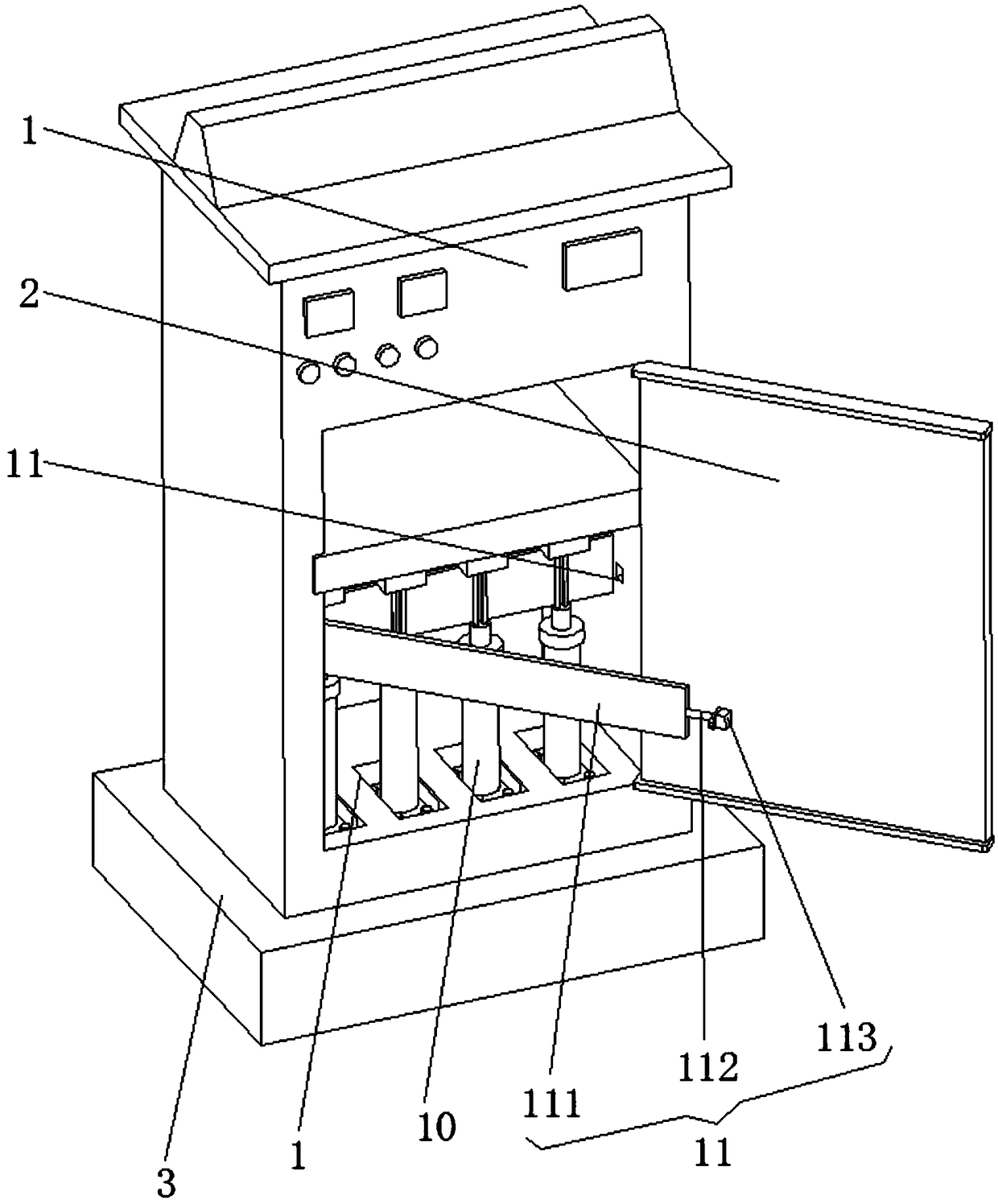
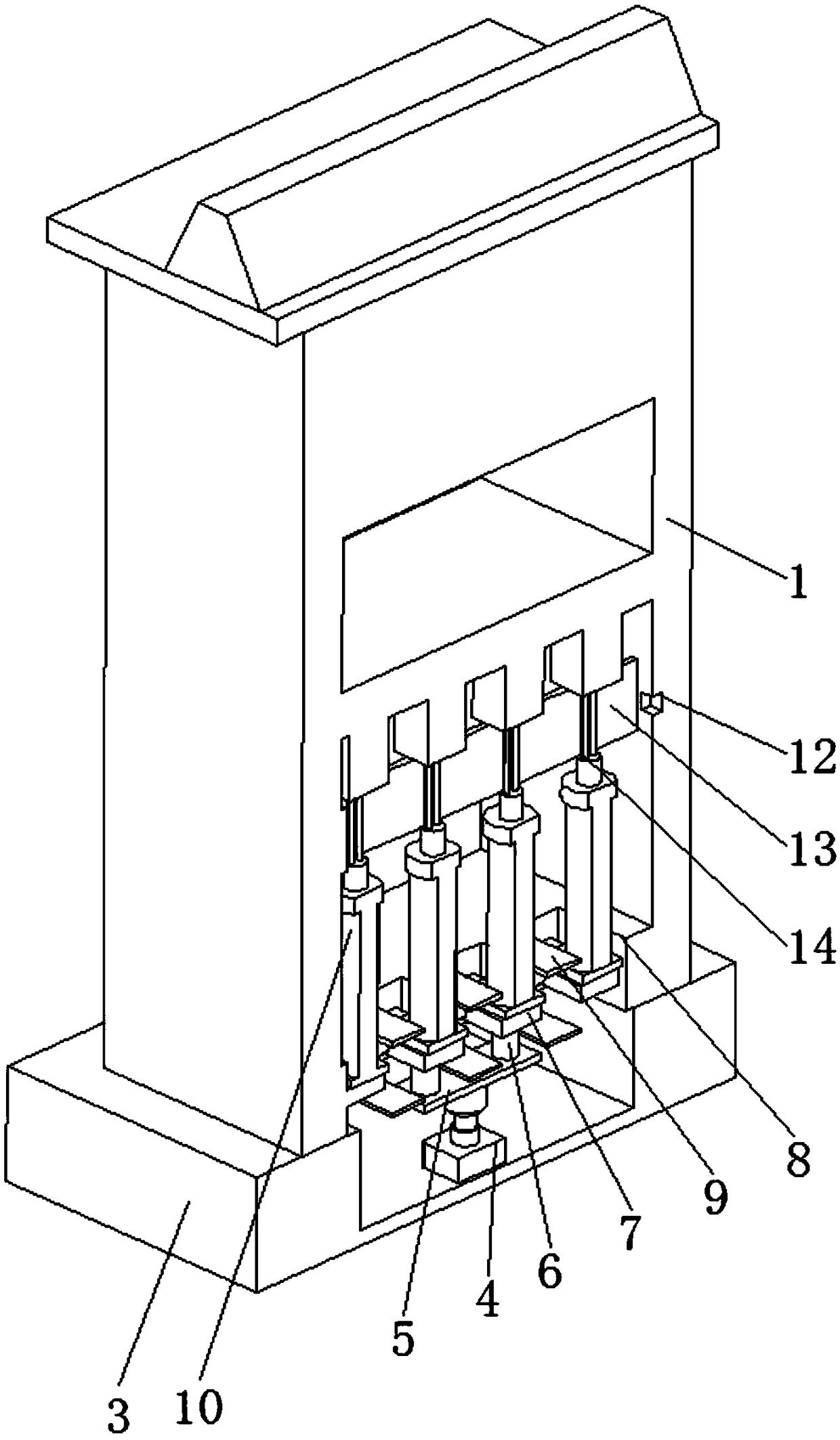
[0033] see Figure 1-3 , a power distribution network reactive power compensation and voltage adjustment device, including a reactive power compensation cabinet 1, a protective door 2 and an accommodating plate 3, a hydraulic rod 4 is fixedly installed at the bottom of the inner cavity of the accommodating board 3, and the pushing end of the hydraulic rod 4 is connected to the The middle part of the bottom end of the receiving plate 5...


PUM


Abstract

The invention relates to the technical field of reactive power compensation and voltage regulation for a distribution network, and discloses a reactive power compensation and voltage adjustment devicefor a distribution network. The reactive power compensation and voltage adjustment device for a distribution network comprises a reactive power compensation cabinet, a protective door and a receivingplate; a hydraulic rod is fixedly mounted on the bottom portion of the inner cavity of the receiving plate, the pushing end of the hydraulic rod is fixedly connected with the middle portion of the bottom end of the receiving plate, two fixing rods are fixedly mounted on the top portion of the receiving plate, the top end of the fixing rod is fixedly connected with the middle portion of the bottomend of a mounting bottom plate, the mounting bottom plate is slidably arranged in an inner cavity of a moving slot, and the moving slot is opened on the middle portion of a fixing substrate. According to the reactive power compensation and voltage adjustment device for the distribution network, with the combination of the hydraulic rod, the receiving plate and the fixing rods, a capacitor mountedon the top portion of the mounting bottom plate is pushed, so that the capacitor slides between the inner cavities of the moving slot and the receiving plate, and stretches the connecting wires at the top end of the capacitor, thereby prevent the connecting wires from bending.

Description

technical field [0001] The invention relates to the technical field of reactive power compensation and voltage adjustment of a distribution network, in particular to a device for reactive power compensation and voltage adjustment of a distribution network. Background technique [0002] The distribution network refers to the power network that receives electrical energy from the transmission network or regional power plants, and distributes it locally or gradually by voltage to various users through distribution facilities. It is a network composed of overhead lines, cables, towers, distribution transformers, isolating switches, reactive power compensators and some ancillary facilities. It plays an important role in distributing electric energy in the power network. During the entire operation of the distribution network, reactive power Compensation and voltage adjustment work occupy an extremely important position. [0003] Reactive power compensation, the full name of reac...

Claims


Application Information

Patent Timeline
IPC IPC(8): H02B1/30H02J3/18
CPCH02B1/30H02J3/1864Y02E40/30
Inventor 马浩程
Owner 杭州新融方科技有限公司
Why Eureka
Try Eureka