Energy storage and phase modifier control system and method for inhibiting direct current continuous phase change failure

A technology of commutation failure and DC control, applied in the direction of power transmission AC network, emergency treatment AC circuit layout, etc., can solve the problems of DC power transmission interruption, threat to the safe and stable operation of the system, multiple DC simultaneous or successive commutation failures, etc. , to achieve the effects of preventing locking, defending against large-scale power outages, and reducing the probability of DC continuous commutation failure

Pending Publication Date: 2018-11-23
NANJING NARI GROUP CORP +2
View PDF3 Cites 5 Cited by
  • Summary
  • Abstract
  • Description
  • Claims
  • Application Information

AI Technical Summary

Problems solved by technology

In the multi-infeed DC transmission system, due to the short electrical distance between the DC inverter stations and the complex interaction between the AC and DC systems, failures in the DC system or the AC system at the receiving end may cause simultaneous or successive commutation failures of multiple DC circuits. and successive commutation failures
When the strength of the receiving end system is weak or the fault of the AC system is serious, the continuous commutation failure of the multi-circuit DC transmission system may lead to the interruption of DC power transmission, which ultimately threatens the safe and stable operation of the entire system.

Method used


Image

  • Energy storage and phase modifier control system and method for inhibiting direct current continuous phase change failure
  • Energy storage and phase modifier control system and method for inhibiting direct current continuous phase change failure

Examples


Embodiment Construction

[0024] In order to further describe the technical features and effects of the present invention, the present invention will be further described below in conjunction with the accompanying drawings and specific embodiments.

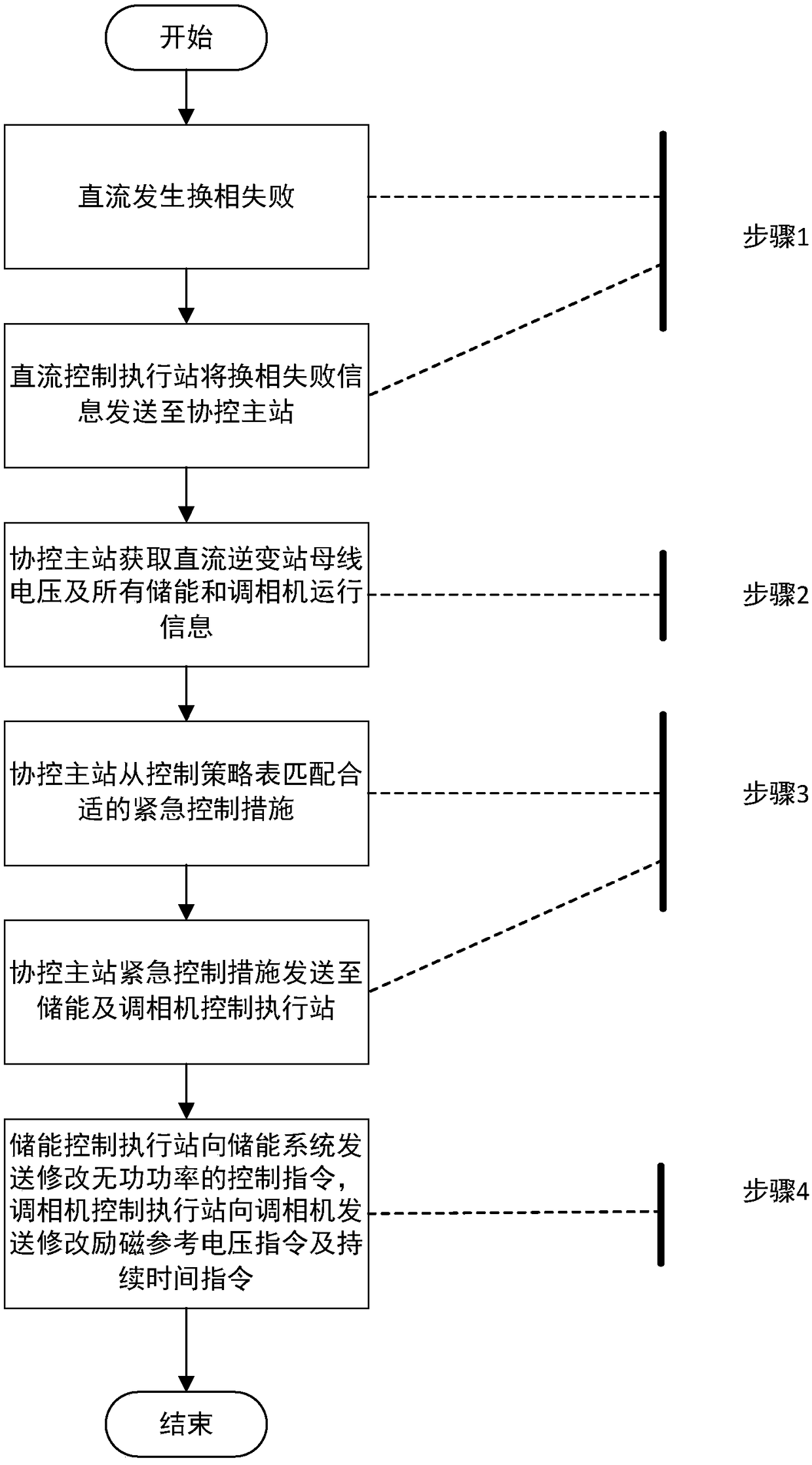
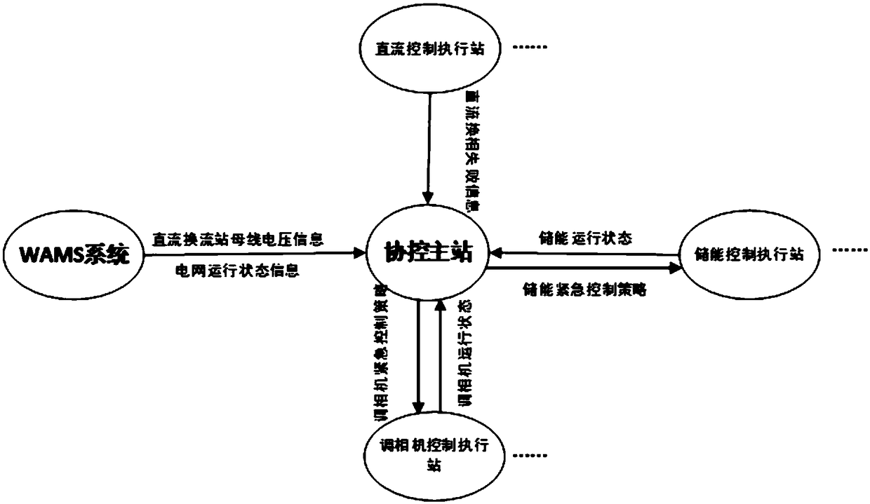
[0025] Such as Figure 1-2 As shown, this embodiment proposes an energy storage and phase regulator control system and method for suppressing DC continuous commutation failure. The so-called coordinated control of energy storage and regulator to suppress DC continuous commutation failure refers to the use of coordinated control of energy storage and regulator to provide reactive power support in the vicinity of the DC converter station after the failure of DC commutation due to a grid fault, reducing the subsequent The probability of commutation failure occurs, avoiding DC blocking due to continuous commutation failure, resulting in large power loss of the grid.

[0026] The energy storage and phase controller coordinated control system for suppressing DC...


PUM


Abstract

The invention discloses an energy storage and phase modifier control system and method for inhibiting direct current continuous phase change failure; the method comprises the steps that direct-currentphase change failure information is sent from a direct-current control execution station to a coordination control master station; the coordination control master station acquires the bus voltage andall the energy storage and phase modifier operation information of a direct-current inverter station which suffers from the phase change failure; the coordination control master station matches a proper emergency measures from a control strategy table and transmits the measure to an energy storage and phase modifier control execution station; an energy storage control execution station transmitsa control instruction for modifying reactive power to an energy storage system, and a phase modifier control execution station transmits an instruction for modifying an excitation reference voltage and a continuation time instruction to the phase modifier to cooperatively complete emergency control. According to the system and method, the energy storage and the phase modifier are cooperatively matched to participate in emergency control of the power grid, so that the probability of the direct-current continuous phase change failure of the direct-current feed-in receiving end power grid can beeffectively reduced, lockout caused by multiple times of phase change failure can be prevented, and a large-area power failure accident caused by multi-direct-current lockout can be prevented.

Description

technical field [0001] The invention belongs to the technical field of electric power systems and automation thereof, in particular to an energy storage and phase adjustment control system and method for suppressing DC continuous commutation failure. Background technique [0002] With the large-scale construction of UHV DC projects, the relationship between AC and DC systems and DC systems is getting closer. During the transition period of UHV power grid construction, the power grid has obvious characteristics of "strong direct current and weak AC", and the safe operation of the system faces greater risks. In the multi-infeed DC transmission system, due to the short electrical distance between the DC inverter stations and the complex interaction between the AC and DC systems, failures in the DC system or the AC system at the receiving end may cause simultaneous or successive commutation failures of multiple DC circuits. and continuous commutation fails. When the strength o...

Claims


Application Information

Patent Timeline
IPC IPC(8): H02J3/36
CPCH02J3/36H02J3/001Y02E60/60
Inventor 吴翃轩宋晓芳周野侯玉强王玉薛峰李威
Owner NANJING NARI GROUP CORP
Why Eureka
Try Eureka