Brushless motor stator and brushless motor

A brushless motor and stator technology, used in synchronous motors with stationary armatures and rotating magnets, electrical components, electromechanical devices, etc. Inter-turn short circuit risk, high efficiency, good manufacturability

Active Publication Date: 2018-11-23
SHENZHEN TUOWEI AUTOMOTIVE TECH CO LTD
View PDF2 Cites 6 Cited by
  • Summary
  • Abstract
  • Description
  • Claims
  • Application Information

AI Technical Summary

Problems solved by technology

[0010] In order to overcome the deficiencies of the prior art, the purpose of the present invention is to solve the problem that the current outlet wires on the stator of the brushless motor are located in different wire slots when winding, and are inside the bridge wires, and need to be manually dialed to the outside, and its efficiency Low and easy to scratch the bridge line, causing technical problems of short circuit

Method used


Image

  • Brushless motor stator and brushless motor
  • Brushless motor stator and brushless motor
  • Brushless motor stator and brushless motor

Examples


Embodiment 1

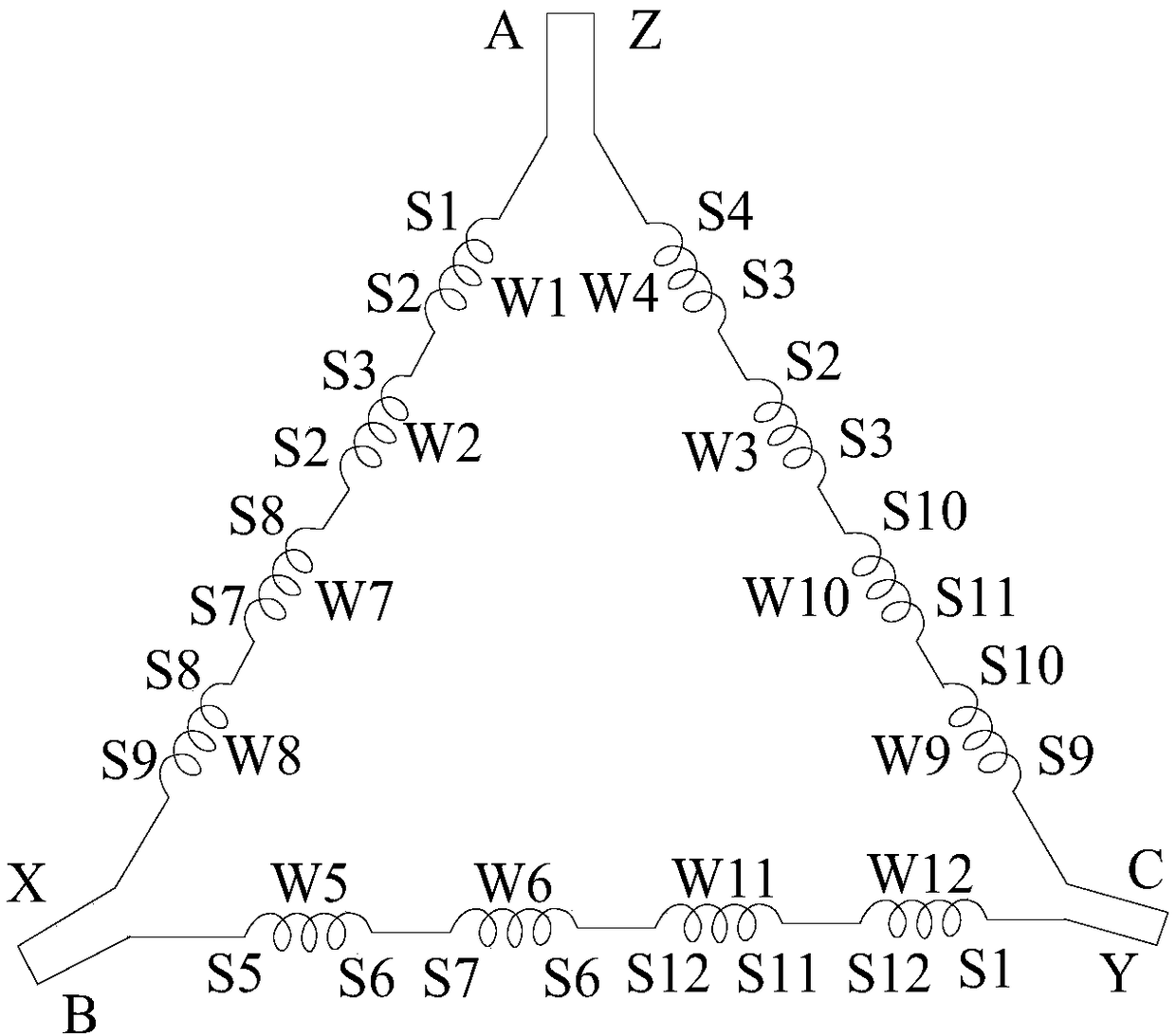
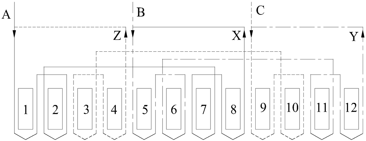
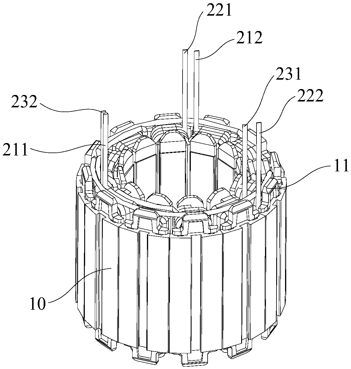
[0042] Such as Figure 3-11 As shown, the first embodiment of the present invention discloses a brushless motor stator. The brushless motor stator includes a stator core assembly 10 and a stator winding 20. The stator winding 20 is wound on the stator core assembly 10, and the stator core assembly 10 There are a plurality of winding teeth 11 spaced apart in the circumferential direction, a slot 12 is provided between any two adjacent winding teeth 11, and the stator winding 20 is accommodated in each slot 12 and wound from each slot 12 Set on each winding tooth 11, the stator winding 20 includes several phase windings, each phase winding includes two lead ends, and the adjacent lead ends of any two adjacent phase windings are located in the same slot 12. Adjacent lead ends of different phases pass through the same slot 12, simplifying the winding structure of the stator winding 20, making it simple in structure, good in manufacturability and high in efficiency.

[0043] Specifica...

Embodiment 2

[0052] Such as Figure 8-11 As shown, the second embodiment of the present invention also discloses another brushless motor stator with a winding structure. The difference from the first embodiment is: a first lead end 211, a second lead end 212, a third lead end 221, The fourth lead end 222, the fifth lead end 231, and the sixth lead end 232 are located on one side of the stator core assembly 10. The first bridge wire 213, the second bridge wire 223, and the third bridge wire 233 are located on the stator iron core. On the other side of the core assembly 10, the bridge wire of the three-phase winding is passed from the other side of the stator lead wire, which is in a different position from the incoming and outgoing wires, effectively avoiding the mutual influence between the two and avoiding the risk of manual threading. It is possible to increase / decrease half-turn coils, thereby increasing the flexibility of adjusting the number of coil turns.

[0053] The invention also di...


PUM


Abstract

The invention discloses a brushless motor stator and a brushless motor. The brushless motor stator comprises a stator core assembly and stator windings, wherein the stator windings are arranged on thestator core assembly in a wound mode. The stator core assembly is provided with a plurality of winding teeth which are distributed at intervals in the circumferential direction, a wire slot is formedbetween any two adjacent winding teeth, and the stator windings are accommodated in the wire slots and are arranged on the winding teeth in a wound mode. The stator windings comprise a plurality of phase windings, each phase winding comprises two lead ends, and the adjacent lead ends of any two adjacent phase windings penetrate out of the same wire slot. The adjacent lead ends of any two adjacentphase windings in the brushless motor stator penetrate out of the same wire slot, the winding structure of the stator windings is simplified, so that the structure is simple, the manufacturability isgood, the efficiency is high, gas bridge wires are not prone to being scratched, and the risk of inter-turn short circuit can be reduced.

Description

Technical field [0001] The present invention relates to the technical field of motors, in particular to a brushless motor stator and a brushless motor. Background technique [0002] In automotive motors (low voltage) and low-power industrial motors, 12-slot brushless motors are widely used. Among them, 12-slot 8-pole matching is the most typical; 12-slot brushless motors with close-pole matching, such as 12-slot 10-pole and 12-slot 14-pole, with the advantages of small self-positioning torque, high winding coefficient, good sine degree and high positioning accuracy, it has received more and more attention, especially in the field of low-voltage automotive motors. In order to improve the performance index of the motor, especially for the brushless motor with an outer diameter of 100mm or less, the segmented stator core is often used to improve the performance index of the motor, but this also causes the complexity of the motor manufacturing process, so how Improving the productio...

Claims


Application Information

Patent Timeline
Patent Type & Authority Applications(China)
IPC IPC(8): H02K1/16H02K3/28
CPCH02K1/165H02K3/28H02K3/522H02K21/16H02K3/12H02K3/48H02K3/50
Inventor 李永斌王新平钟国威
Owner SHENZHEN TUOWEI AUTOMOTIVE TECH CO LTD
Why Eureka
Try Eureka