Site horizontal lamination edge segment iron core process of turbo generator

A technology of turbogenerator and iron core, which is applied in the manufacture of stator/rotor body, etc., which can solve the problems of long cycle, high cost and difficulty in repair process

Active Publication Date: 2018-11-23
HARBIN ELECTRIC MASCH CO LTD
View PDF4 Cites 3 Cited by
  • Summary
  • Abstract
  • Description
  • Claims
  • Application Information

AI Technical Summary

Problems solved by technology

The stator core (1) is vertically stacked in the factory, and the stator core (1) must also be erected when re-stacking the side core (2) according to the conventional process, and this is done at the core stacking station. This requires the generator stator to be transported back to the factory, and the repair process is costly, difficult and long-term

Method used


Image

  • Site horizontal lamination edge segment iron core process of turbo generator
  • Site horizontal lamination edge segment iron core process of turbo generator
  • Site horizontal lamination edge segment iron core process of turbo generator

Examples


Embodiment Construction

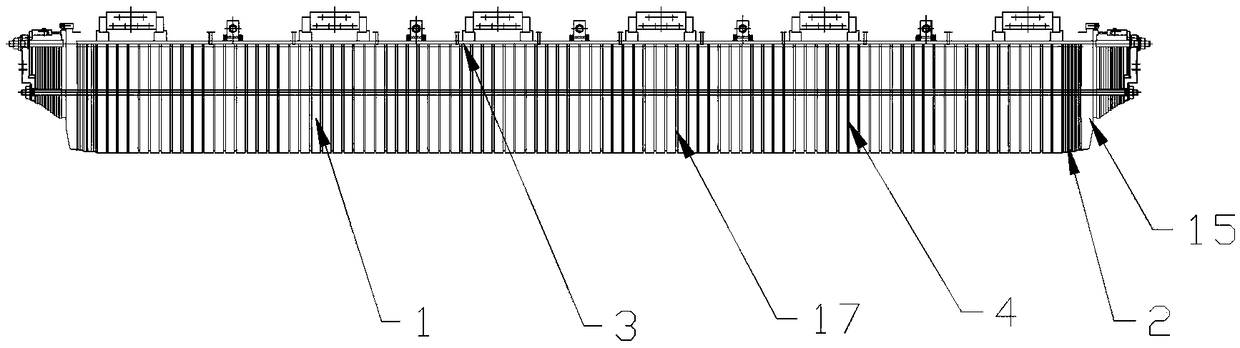
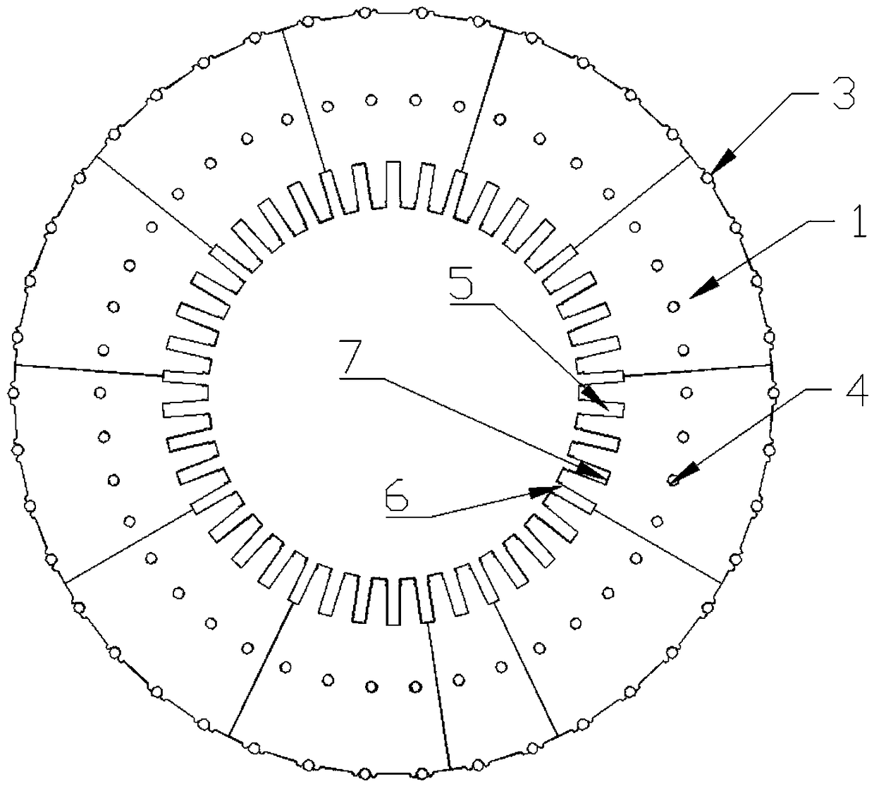
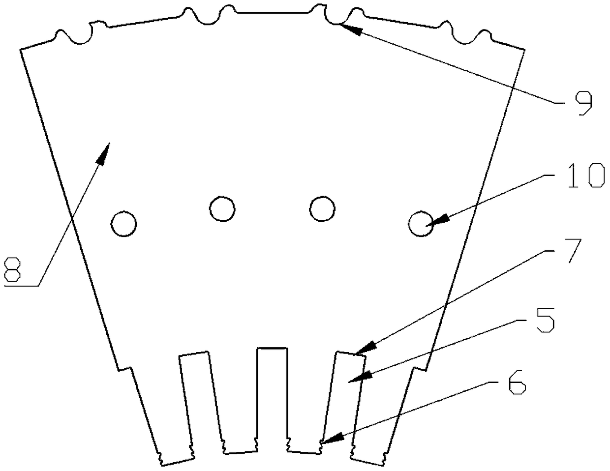
[0025] On-site horizontal stacking side section iron core technology for turbogenerator stator. Its technological implementation process is as follows:

[0026] 1) Before stacking the side section core 2, install all the positioning tools in place first, position the positioning slot 9 on the back of the stator core 1 with the positioning screw 3, and position the slot wedge slot 6 of the lower wire slot 5 with the slot wedge slot positioning rod 12 and extend it. Out of a length greater than the thickness of the side core 2, the slot bottom 7 of the lower wire slot 5 is positioned with a slot-like rod 11 and stretched out to a length greater than the thickness of the side segment iron core 2, the slot-like rod 11 is pushed against the slot bottom 7 by the top wire 13, The groove wedge groove positioning rod 12 and the groove sample rod 11 can coordinate the tangential and radial two-way positioning of the lower wire groove 5, and a set of groove wedge groove positioning rod 1...


PUM


Abstract

The invention relates to a site horizontal lamination edge segment iron core process of a turbo generator. In order to overcome influence of a punching sheet and press finger assembly gravity on the size and the linearity of a groove during the horizontal lamination process, a lower slot is positioned by a positioning screw rod, a groove-type rod, a slot groove and a positioning rod, shaping is performed on a center-penetrating screw rod hole by a tool center-penetrating screw rod, and the press finger assembly quality is ensured by the positioning screw rod, the groove-type rod, the slot groove, the positioning rod and a press finger fixing tool after lamination.

Description

Technical field: [0001] The invention relates to a technology for on-site horizontal stacking of side segment iron cores of a steam turbine generator. Background technique: [0002] After a period of on-site operation of the turbo-generator, a few units may experience serious loosening of the stator core (1) or even broken teeth. The location of the fault is generally on the side core (2). The repair process for these faults can be handled locally Or the methods such as stacking the side section iron core (2) again thoroughly. The stator core (1) is vertically stacked in the factory, and the stator core (1) must also be erected when re-stacking the side core (2) according to the conventional process, and this is done at the core stacking station. This requires the generator stator to be transported back to the manufacturing plant, and the repair process is costly, difficult and long-term. Invention content: [0003] The purpose of the present invention is to provide a pr...

Claims


Application Information

Patent Timeline
Patent Type & Authority Applications(China)
IPC IPC(8): H02K15/02
CPCH02K15/02
Inventor 刘俊英董巍张虹丁旭东孙浩然王巍
Owner HARBIN ELECTRIC MASCH CO LTD
Why Eureka
Try Eureka