
Optical module for local loopback module

A loopback test and optical module technology, applied in the direction of optical fiber transmission, electromagnetic wave transmission system, electrical components, etc., can solve the problems of unable to cover the host switch application, not supporting the corresponding rate expansion of debugging mode, increasing the test cost, etc., to achieve saving The effect of testing cost and time, reducing the difficulty of system testing, and improving testing efficiency

Active Publication Date: 2018-11-23
成都新易盛通信技术股份有限公司 +1
View PDF12 Cites 11 Cited by
  • Summary
  • Abstract
  • Description
  • Claims
  • Application Information

AI Technical Summary

Problems solved by technology

The existing QSFP28Loopback test optical module adopts NRZ modulation mode, which does not support debugging modes such as PAM-4 and its corresponding rate expansion. In addition, each QSFP28Loopback test optical module only corresponds to one power consumption level, such as the host end has different power consumption Level of test requirements, it is necessary to customize a variety of Loopback modules with different power consumption for testing, which not only increases the test cost, but also brings a lot of inconvenience to the test work
[0005] At present, major network communication companies in the world have different attitudes towards the development direction of high-speed modules in the future. Some believe that QSFP-DD series high-speed optical modules will become mainstream products, while others believe that OSFP or CFP series high-speed optical modules will dominate market development. Trend; for the development trend of the next generation of high-speed optical modules, QSFP-DD, OSFP, and CFP series optical modules will rise and develop at the same time when there is no consensus around the world; the existing single type of Loopback test optical modules will not be able to cover The application of most host-side switches

Method used


Image

  • Optical module for local loopback module
  • Optical module for local loopback module
  • Optical module for local loopback module

Examples


Embodiment Construction

[0033] In the following, the present invention will be further described in detail in conjunction with the accompanying drawings and embodiments, so as to make the purpose, technical solutions and advantages of the present invention more clear. It should be understood that the specific embodiments described here are only used to explain the present invention, not to limit the present invention.

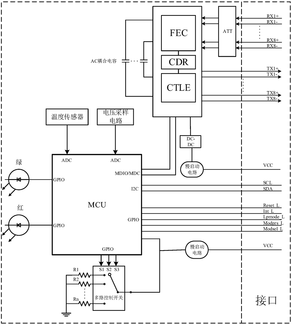
[0034] figure 1 An optical module used for a local loopback test according to an exemplary embodiment of the present invention is shown. The optical module of this embodiment mainly includes: a plurality of interfaces encapsulated according to a preset protocol, an attenuation circuit ATT, a CDR module, a micro control unit MCU, a multi-channel control switch, and a plurality of load resistors. Among them, the preset protocol can be double-density four-channel small form-factor pluggable module (QSFP-DD) multi-source agreement (MSA), small-package hot-swap Plugging and unplugging SF...


PUM


Abstract

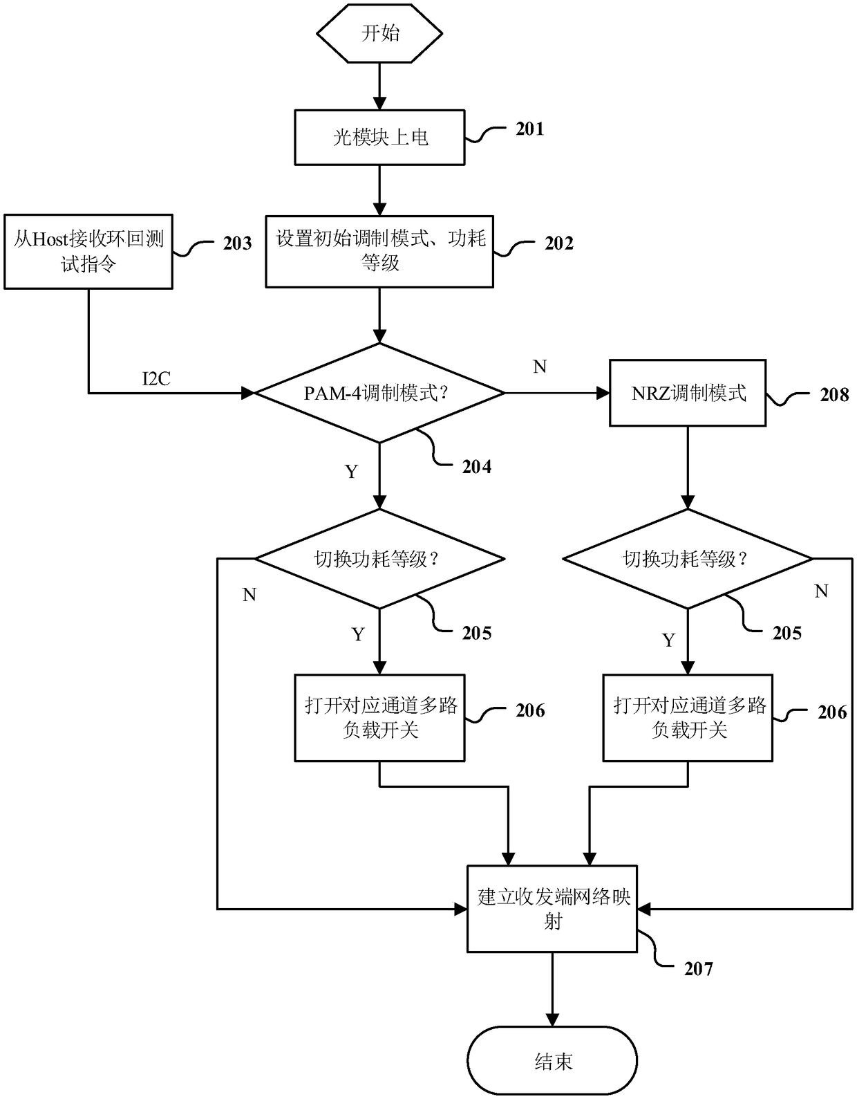
The present invention discloses an optical module for a local loopback module. The optical module can simulate test application environments in different power consumption conditions to accurately collect feedback related information in real time and is suitable for network devices with various different modulation types and rate in different link attenuation conditions so as to shorten the test time and reduce the test cost while improving the test precision and the accuracy. The optical module comprises a plurality of interfaces, an attenuator circuit ATT, a CDR module, a micro control unit(MCU), a multi-path control switch and a plurality of load resistors which are packaged according to a preset protocol, wherein the MCU is configured to set an initialization modulation module and a power consumption grade of the optical module according to the preset protocol to control the CDR module to employ a PAM-4 modulation mode or an NRZ modulation mode and switch the rate of each signal interface according to the modulation mode; and moreover, a corresponding load power consumption value is controlled to be set, and the CDR module is controlled to establish network mapping between input / output signal interfaces.

Description

technical field [0001] The invention relates to the technical field of optical fiber communication, in particular to an optical module used for local loopback Loopback (Loopback refers to local loopback in this article) test. Background technique [0002] In recent years, with the rapid development of mobile communication technology, the fifth-generation mobile communication technology "5G" will gradually enter our lives. As the carrier of the 5G communication system, high-speed optical modules and corresponding routers, switches and other network equipment will be used by a large number of use. Most of the existing network devices use non-return-to-zero code NRZ mode for signal transmission and interaction, that is, two signal levels are used to represent 0 and 1 information of digital logic signals, and each symbol period can transmit 1 bit of logic information ; and the pulse amplitude modulation PAM signal can use more signal levels, so that each symbol period can trans...

Claims


Application Information

Patent Timeline
Patent Type & Authority Applications(China)
IPC IPC(8): H04B10/079H04B10/25
CPCH04B10/0795H04B10/25891
Inventor 彭向伟曹阳肖影黄晓雷
Owner 成都新易盛通信技术股份有限公司
Learn More