Dynamic load reduction device for backpacks

A dynamic load and knapsack technology, which is applied to travel or camping equipment, household appliances, travel bags, etc., can solve the problem of lightening, and achieve the effect of low cost, compact structure and light weight

Pending Publication Date: 2018-11-27
SOUTH CHINA UNIV OF TECH
View PDF5 Cites 19 Cited by
  • Summary
  • Abstract
  • Description
  • Claims
  • Application Information

AI Technical Summary

Problems solved by technology

According to the novelty search on the Internet, there is no device similar to the present inven

Method used


Image

  • Dynamic load reduction device for backpacks
  • Dynamic load reduction device for backpacks

Examples


Embodiment Construction

[0016] The present invention will be further described below in conjunction with specific examples, but is not limited thereto.

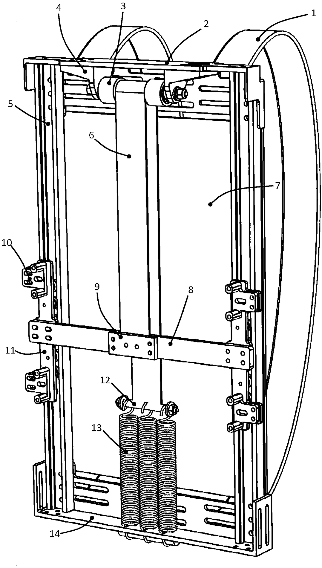
[0017] Such as figure 1 Shown is a structural schematic diagram of a backpack dynamic load relief device of the present invention, including an upper beam 2, a lower beam 14, a guide rail 5, a guide wheel 3, a guide wheel support seat 4, a sliding connecting frame, a spring 13, and a spring connecting shaft 12. The stay rope 6 and the backboard 7, the upper beam 2 and the lower beam 14 are connected by the guide rail 5, and the guide rail 5 is installed at both ends of the upper beam 2 and the lower beam 14, and is perpendicular to the upper beam and the lower beam. Beam, the guide wheel support seat 4 is installed on the upper beam 2, connected with the guide wheel 3, the backboard is fixedly connected to the upper beam 2 and the lower beam 14, and the two ends of the sliding connection frame are respectively installed on the guide rails 5 on both ...


PUM


Abstract

The invention discloses a dynamic load reduction device for backpacks, comprising an upper cross beam, a lower cross beam, guide rails, guide wheels, guide wheel supports, a sliding connection rack, springs, a spring connection shaft, a pull rope and a back plate. The upper cross beam is connected with the lower cross beam through the guide rails; the guide rails are mounted at the two ends of theupper and lower cross beams and are perpendicular to the upper and lower cross beams; the guide wheel supports are mounted on the upper cross beam and are connected with the guide wheels; the back plate is fixedly connected with the upper and lower cross beams; two ends of the sliding connection rack are fitted to the guide rails on the two sides respectively; one ends of the springs are fixed tothe lower cross beam; the other ends of the springs are fixedly connected with the spring connection shaft; one end of the pull rope is connected with the spring connection shaft, and the other end of the pull rope is passed around the guide wheels and is fixed to the sliding connection rack. The dynamic load reduction device for backpacks reduces load by making use of frequency and phase differences of damping mass and the vibrating human body, operating efficiency is improved, and the burden of field operators is reduced.

Description

technical field [0001] The invention relates to the field of human body wearable equipment, in particular to a backpack dynamic load relief device. Background technique [0002] With the modernization of national defense and the needs of scientific research, soldiers, scientific research personnel, etc. need to carry a variety of equipment, such as a series of electronic equipment, batteries, etc., when working in the field. The heavy equipment puts the physical strength of soldiers and scientific research personnel to a severe test, which is not conducive to the smooth progress of operations. Therefore, it is very necessary and meaningful to find a device that can reduce the burden on the bearer of the heavy equipment. According to new searches on the Internet, there is no device similar to the present invention for reducing the dynamic load on the human trunk when the human body is carrying heavy objects. Contents of the invention [0003] In view of this, in order to ...

Claims


Application Information

Patent Timeline
IPC IPC(8): A45F3/08A45F3/10
CPCA45F3/08A45F3/10
Inventor 谢龙汉
Owner SOUTH CHINA UNIV OF TECH
Why Eureka
Try Eureka