
Test anti-blowout safety valve

A safety valve and anti-blowout technology, which is applied in the field of safety valves, can solve the problems of cumbersome installation and use, complex structure, and high cost, and achieve the effects of preventing oil leakage, simple operation, and simple structure

Inactive Publication Date: 2018-11-27
FUNING COUNTY PETROL MECHANICAL LIMITED
View PDF0 Cites 5 Cited by
  • Summary
  • Abstract
  • Description
  • Claims
  • Application Information

AI Technical Summary

Problems solved by technology

In addition to leakage caused by perforated oil pipelines and corrosion and perforation, there are also leakages caused during normal production when pressure gauges or sampling meters are replaced, which seriously interfere with normal production. Therefore, oil pipeline leakage is an urgent issue solved problem
[0003] At present, there are pressure gauges and sampling gauges on the oil pipeline. The existing pressure gauges are installed with shut-off valves on the oil pipelines. This installation method has the following defects: when replacing the pressure gauge, the internal thread shut-off valve needs to be closed to prevent sampling The environment around the wellhead is polluted by the leakage of the output fluid. If the internal thread stop valve fails to close tightly, the phenomenon of leakage of the production fluid will occur and pollute the environment around the wellhead. In addition, most oil production wells are in the field, and once the pressure gauge is damaged, The phenomenon that the production fluid leakage will pollute the environment around the wellhead
The current wellhead blowout prevention device is composed of valve body, valve seat and check valve, which solves the above problems in a certain procedure, but its complex structure, high cost, cumbersome installation and use make it inconvenient to use. Therefore, we propose a Types of Test Blowout Preventer Safety Valves

Method used


Image

  • Test anti-blowout safety valve
  • Test anti-blowout safety valve

Examples


Embodiment Construction

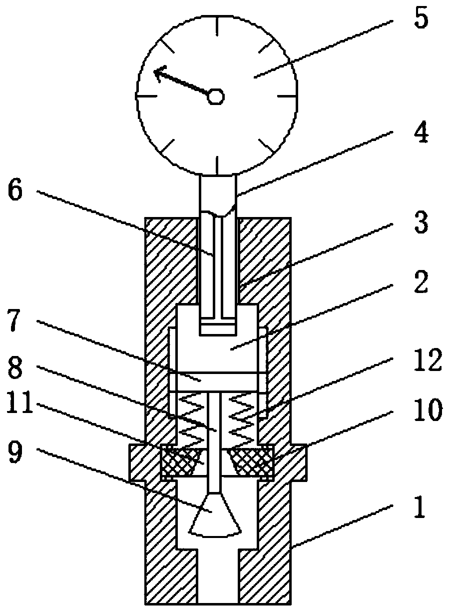
[0015] The following will clearly and completely describe the technical solutions in the embodiments of the present invention with reference to the accompanying drawings in the embodiments of the present invention. Obviously, the described embodiments are only some, not all, embodiments of the present invention. Based on the embodiments of the present invention, all other embodiments obtained by persons of ordinary skill in the art without making creative efforts belong to the protection scope of the present invention.

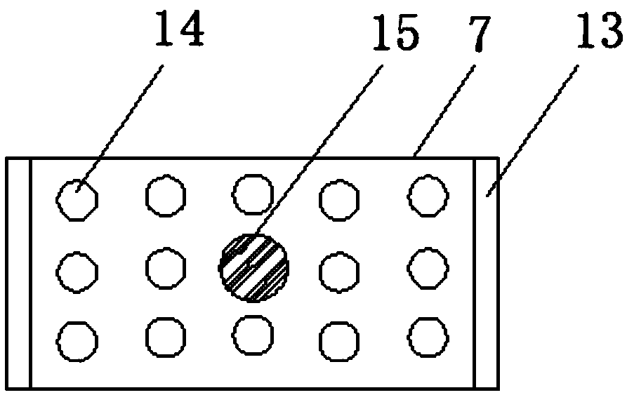
[0016] see Figure 1-2 , the present invention provides a technical solution: a test blowout prevention safety valve, including a safety valve body 1, a groove 2 is opened on the safety valve body 1, through holes 3 are opened on the top and bottom of the safety valve body 1, and The two groups of through holes 3 communicate with the groove 2, the top through hole 3 is internally threaded with a rotating rod 4, the top of the rotating rod 4 is equipped with a ...


PUM


Abstract

The invention discloses a test anti-blowout safety valve in the technical field of safety valves. The test anti-blowout safety valve comprises a safety valve body, wherein a groove is formed in the safety valve body, through holes are formed in the top and bottom of the safety valve body, the through hole in the top is internally in threaded connection with a rotating rod, a T-shaped hole is formed in a central axis of the rotating rod, a baffle is slidably arranged in the groove, a push rod is arranged at the bottom of the baffle, a piston is arranged at the bottom of the push rod, a valve seat is arranged in the groove, the valve seat is fixed to the safety valve body through a bolt, a taper hole is formed in the valve seat, and springs are arranged on the left and right sides of the topof the valve seat; the rotating rod rotationally moves up in the through hole in the top by screwing a pressure gauge, the baffle slides upward in the groove under the elastic recovery of the springs, so that the push rod moves upward, therefore the piston can block the taper hole to play a role in blowout prevention and prevent oil leakage from polluting the surrounding environment, the operation is simple, and the cost is lower.

Description

technical field [0001] The invention relates to the technical field of safety valves, in particular to a test blowout prevention safety valve. Background technique [0002] In the process of oilfield development, the monitoring of oil pipelines is also very important, and leakage is the main fault in the operation of oil pipelines. In addition to leakage caused by perforated oil pipelines and corrosion and perforation, there are also leakages caused during normal production when pressure gauges or sampling meters are replaced, which seriously interfere with normal production. Therefore, oil pipeline leakage is an urgent issue solved problem. [0003] At present, there are pressure gauges and sampling gauges on the oil pipeline. The existing pressure gauges are installed with shut-off valves on the oil pipelines. This installation method has the following defects: when replacing the pressure gauge, the internal thread shut-off valve needs to be closed to prevent sampling Th...

Claims


Application Information

Patent Timeline
Patent Type & Authority Applications(China)
IPC IPC(8): F16K1/32F16K1/00
CPCF16K1/32F16K1/00
Inventor 周为余周正权
Owner FUNING COUNTY PETROL MECHANICAL LIMITED
Learn More