Metal rigidity seal ball valve

A technology of hard sealing and ball valves, applied in valve details, valve devices, valve housing structures, etc., can solve problems such as high maintenance costs, reduced service life of valves, and damage to valve sealing, so as to reduce maintenance costs and prolong service life , Improve the effect of sealing effect

Pending Publication Date: 2018-11-27
KUSN WEISA VALVE
View PDF6 Cites 9 Cited by
  • Summary
  • Abstract
  • Description
  • Claims
  • Application Information

AI Technical Summary

Problems solved by technology

For conventional ball valves, the sealing surface of the valve seat is generally made of soft materials, but for crude oil containing hard solid particles, fine particles in the medium are easily bonded to the spherical surface to form scaling, and these particles will enter the spherical surface and the valve seat during the valve switch process. Between the sealing surfaces, it will cause continuous wear to the sealing surface, destroy the sealing performance of the valve, and cause leakage of the sealing surface; seal leak
In addition, due to the sulfur content in crude oil, it has a corrosive effect on pipelines, and the sealing area of ​​the valve is exposed to acidic conditions for a long time, which will also be corroded, the sealing performance of the valve will also be reduced, and the service life of the valve will be reduced, resulting in frequent maintenance and high maintenance costs

Method used


Image

  • Metal rigidity seal ball valve
  • Metal rigidity seal ball valve
  • Metal rigidity seal ball valve

Examples


Embodiment

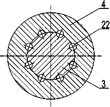
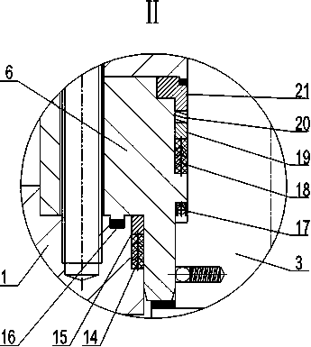
[0038] Figure 1 to Figure 4 In the embodiment, the valve body includes a middle valve body 1 located on the outer periphery of the ball, and a left valve cover and a right valve cover 2 respectively connected to both ends of the middle valve body 1; the left valve seat and the right valve seat 5 respectively pass the first sealing The assembly sealably connects the left and right bonnets. The middle valve body 1 and the left and right valve covers 2 are detachably connected by stud nuts, and the assembly is convenient and simple.

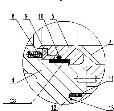
[0039] refer to image 3 As shown, the metal protection layer 23 on the outside of the first sealing ring is made of stainless steel, and is surfacing welded on the sealing surface of the left valve cover or the right valve cover 2 below the active area of ​​the sealing ring. The stainless steel material has strong corrosion resistance, which can prevent the sealing area from damaging the first sealing ring due to corrosion, improves the sealing ...


PUM


Abstract

The invention discloses a metal rigidity seal ball valve which comprises a valve, a valve seat, a valve stem and a ball. The ball is positioned in a ball cavity in the valve; the valve seat comprisesa left valve seat and a right valve seat, the left valve seat and the right valve seat are symmetrically arranged on two sides of the ball, and scraper mechanisms are arranged at the positions, whichare butted to the ball, of the valve seat; seal surfaces between the valve seat and the valve are in the shapes of multiple levels of steps which are matched with one another, and a first sealing assembly is arranged between every two corresponding seal surfaces; each first seal assembly comprises a first elastic component, a clamping component and a first seal ring; the clamping components are provided with L-shaped axial sections, two ends of each first elastic component are butted to the valve and a vertical arm of the corresponding L-shaped clamping component, a corner of each L-shaped clamping component is clamped on one of the levels of steps of the corresponding seal surface of the valve seat, the first seal rings are mounted between the tail ends of transverse arms of the L-shapedclamping components and the seal surfaces of the valve seat, and metal protection layers are arranged on the seal surfaces of the valve and are positioned on the outer sides of the first seal rings. The metal rigidity seal ball valve has the advantages that seal structures on the seal surfaces are improved, accordingly, seal effects can be enhanced, the service lives of seal components can be prolonged, elastic components can be protected, and the metal rigidity seal ball valve is particularly applicable to working conditions with crude oil used as a medium.

Description

technical field [0001] The invention relates to the technical field of metal hard-sealed ball valves, in particular to a metal-hard-sealed ball valve suitable for crude oil medium. Background technique [0002] With the development of industrialization, the requirements for valves are getting higher and higher. Ball valves use spheres as the opening and closing parts, which have the advantages of small flow resistance, small pressure loss, reliable sealing, and easy operation, and are trusted by customers, and are widely used in oil and gas pipelines. [0003] In the case of crude oil, there are solid particles and acidic elements. For conventional ball valves, the sealing surface of the valve seat is generally made of soft materials, but for crude oil containing hard solid particles, fine particles in the medium are easily bonded to the spherical surface to form scaling, and these particles will enter the spherical surface and the valve seat during the valve switch process...

Claims


Application Information

Patent Timeline
Patent Type & Authority Applications(China)
IPC IPC(8): F16K5/06F16K5/20F16K27/06
CPCF16K5/0605F16K5/0663F16K5/0689F16K5/201F16K27/067
Inventor 杨青朱建明周向青
Owner KUSN WEISA VALVE
Why Eureka
Try Eureka