Optical-layer service layering model configuration method and system in network management system

A technology of layered model and network management system, applied in the field of computer communication, can solve the problems of implementation and management, reduce user experience, etc., and achieve the effect of simplifying complexity and improving user experience

Active Publication Date: 2018-11-27
FENGHUO COMM SCI & TECH CO LTD
View PDF4 Cites 9 Cited by
  • Summary
  • Abstract
  • Description
  • Claims
  • Application Information

AI Technical Summary

Problems solved by technology

In the current network management system, the configuration of optical layer services is not completely implemented and managed according to the standard three levels, which makes the upper layer integrated network management of operators such as telecom and the centralized

Method used


Image

  • Optical-layer service layering model configuration method and system in network management system
  • Optical-layer service layering model configuration method and system in network management system
  • Optical-layer service layering model configuration method and system in network management system

Examples


Embodiment 1

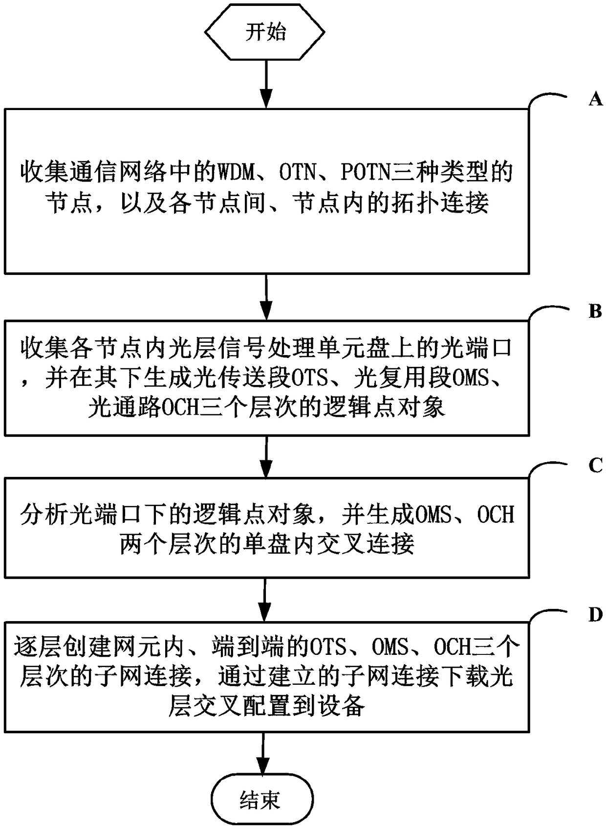
[0077] see figure 1 As shown, the embodiment of the present invention provides a method for configuring a layered model of an optical layer service in a network management system, including the following steps:

[0078] Step A, collect WDM, OTN, POTN three types of nodes in the communication network, and the topological connections between each node and within the node;

[0079] Step B, collect the optical ports on the optical layer signal processing unit disk in each node, and generate logical point objects at three levels: optical transmission section OTS, optical multiplexing section OMS, and optical channel OCH;

[0080] Step C, analyzing the logical point objects under the optical port, and generating cross-connects in a single disk at two levels of OMS and OCH;

[0081] Step D: Create subnet connections in the network element and end-to-end OTS, OMS, and OCH layers layer by layer, and download the optical layer cross-connection configuration to the device through the es...

Embodiment 2

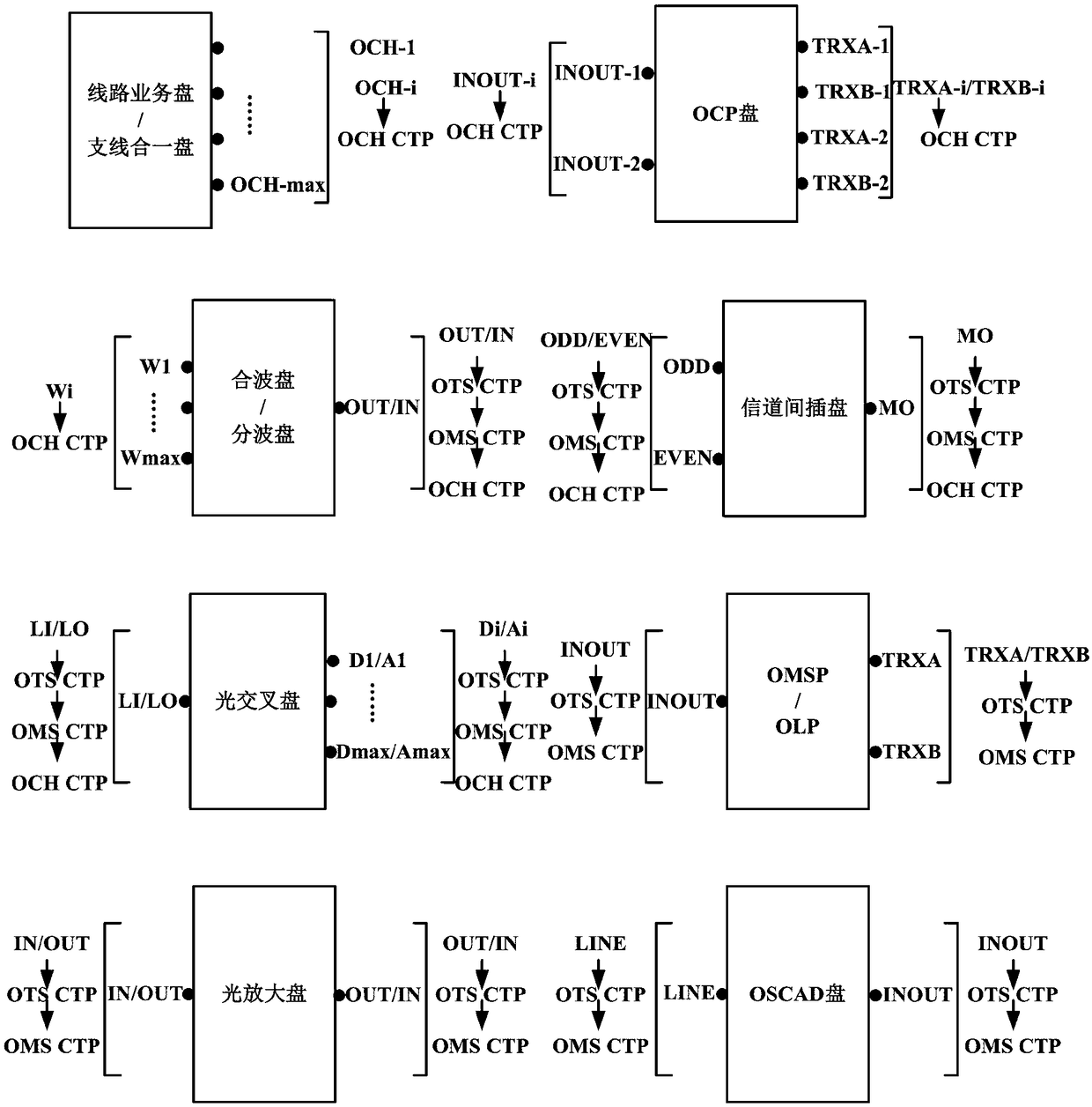
[0116] see figure 2 As shown in , a schematic diagram of the logical point object model under the optical port of the optical layer signal processing unit is given. OCH CTP is automatically generated as a logical point object under the line service disk, the line optical port of the branch line integration disk, the line, work, and protection optical ports of the OCP disk, and the single-wavelength optical port of the multiplexing / demultiplexing disk; Under the composite wave port of the demultiplexing disk, inter-channel insertion disk, and optical cross-connect disk, three logical point objects, OTS CTP, OMS CTP, and OCH CTP, are automatically generated layer by layer; in the composite wave port of the optical amplifier disk, OSCAD disk, and OLP Under the line, working, and protection optical ports of disks and OMSP disks, two logical point objects, OTS CTP and OMS CTP, are automatically generated layer by layer.

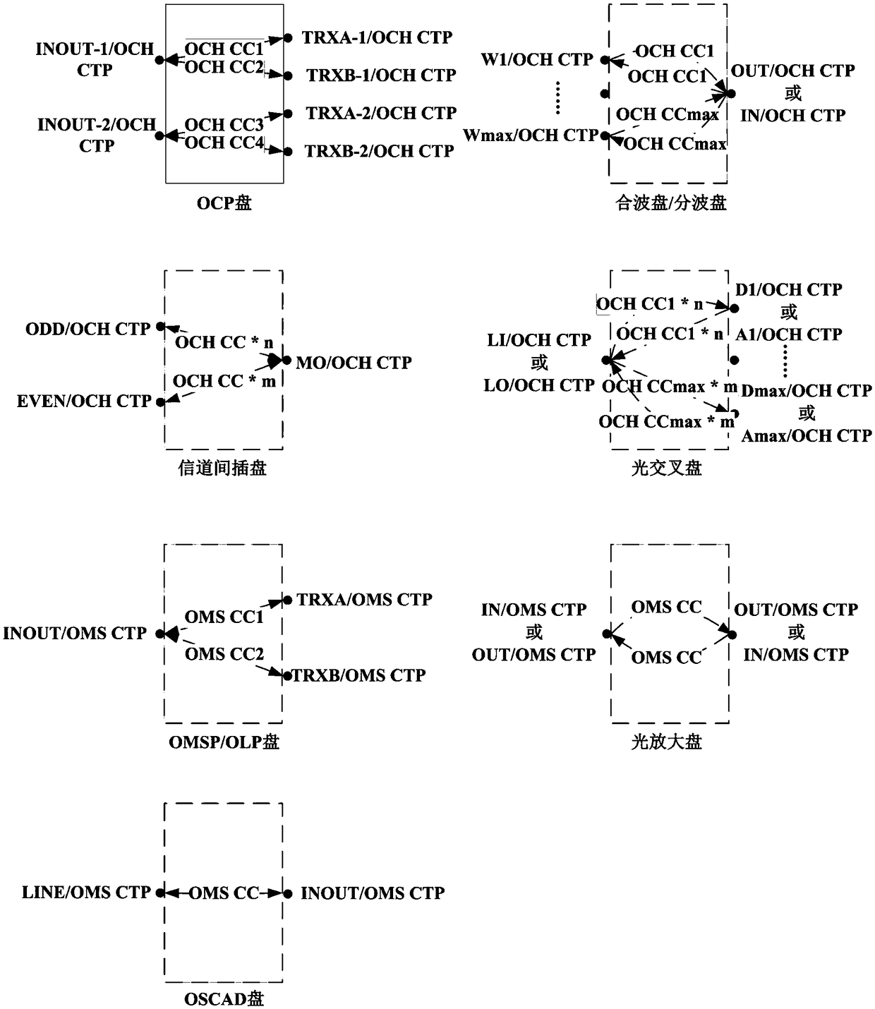
[0117] see image 3 As shown in , a schematic diagram of ...

Embodiment 3

[0121] On the basis of Embodiment 1, the topological connection between nodes in step A refers to the optical fiber connection between two adjacent nodes, which will be displayed in the network management topology diagram; the topological connection within a node refers to the fiber connection between two adjacent nodes. The optical fiber connection between two single disks is not displayed in the network management topology diagram.

[0122] Furthermore, in actual operation, it is first necessary to analyze the nodes in the communication network, as well as the fiber connections within and between nodes, and complete the creation of the optical layer node data set and the topological connection data set.

[0123] Further, the optical layer signal processing unit disk in step B refers to the line service disk, the branch line integration disk, the combination and separation disk, the optical cross disk, the optical protection disk, and the optical amplifier disk; wherein, the c...


PUM


Abstract

The invention discloses an optical-layer service layering model configuration method and system in a network management system and relates to the technical field of computer communication. The optical-layer service layering model configuration method comprises the following steps: collecting three types of nodes including WDM (Wavelength Division Multiplexing), an OTN (Open Transport Network) anda POTN (Packet Optical Transport Network) in a communication network in a communication network, and topological connection between the nodes and in the nodes; collecting an optical port in each nodeon an optical-layer signal processing unit disc, and generating logic point objects of three levels including an optical transmission section OTS, an optical multiplexing section OMS and an optical channel OCH under the optical port; analyzing the logic point objects under the optical port and generating single-disc internal crossed connection of two levels including the OMS and the OCH; establishing end-to-end sub-network connection of the three levels including the OTS, the OMS and the OCH in network elements layer by layer; crossly configuring a downloading optical layer to equipment underthe established sub-network connection, so that the complexity of processing service data by an upper layer is simplified and the user experience is remarkably improved.

Description

technical field [0001] The invention relates to the technical field of computer communication, in particular to a method and system for configuring a layered model of an optical layer service in a network management system. Background technique [0002] With the rapid development of optical fiber communication technology, the early WDM (Wavelength Division Multiplexing) technology has changed the ultra-low utilization of only one wavelength channel in one optical fiber, making full use of the huge bandwidth resources of the optical fiber ( low-loss band), so that the transmission capacity of an optical fiber increases several times to dozens of times compared with single-wavelength transmission, thereby increasing the transmission capacity of the optical fiber and reducing costs, which has great application value and economic value. However, as application scenarios become more and more extensive and complex, OTN (Optical Transport Network, Optical Transport Network) as the ...

Claims


Application Information

Patent Timeline
IPC IPC(8): H04L12/24H04Q11/00
CPCH04L41/12H04Q11/0062H04Q2011/0075H04Q2011/0079
Inventor 李琪刘鑫
Owner FENGHUO COMM SCI & TECH CO LTD
Why Eureka
Try Eureka