Floor mopping device with rotary limiting structure

A technology of rotation limit and limit structure, which is applied in the direction of cleaning carpets, cleaning floors, household appliances, etc., and can solve the problems of being unable to perform other activities at the same time and reducing user experience.

Active Publication Date: 2018-11-30
JIANGSU MIDEA CLEANING APPLIANCES +1
View PDF9 Cites 2 Cited by
  • Summary
  • Abstract
  • Description
  • Claims
  • Application Information

AI Technical Summary

Problems solved by technology

[0002] Among the existing electric mops, such as figure 1 As shown, the tow bar 4' and the mopping head 2' are basically connected by the rotating shaft 6' and the fixed fulcrum, wherein the connecting end of the towing bar 4' is a single rotating shaft 6', and the connecting end of the mopping head 2' is set in line with the rotating shaft. 6' match the fixed fulcrum, the rotating shaft 6' rotates in the fixed fulcrum to realize the relative rotation between the mopping bar 4' and the mopping head 2', but there is no limit structure between the mopping head 2' and the mopping bar 4', when the user When the electric mop is not operated, the mop bar 4' will automatically rotate and fall under the action of its own gravity, so that the user must always hold the mop bar 4' to ensure that the mop bar 4' is upright, so that the user cannot perform cleaning at the same time Other activities bring many changes to users and reduce user experience

Method used


Image

  • Floor mopping device with rotary limiting structure
  • Floor mopping device with rotary limiting structure
  • Floor mopping device with rotary limiting structure

Examples


Embodiment Construction

[0076] In order to understand the above-mentioned purpose, features and advantages of the present invention more clearly, the present invention will be further described in detail below in conjunction with the accompanying drawings and specific embodiments. It should be noted that, in the case of no conflict, the embodiments of the present application and the features in the embodiments can be combined with each other.

[0077] In the following description, many specific details are set forth in order to fully understand the present invention. However, the present invention can also be implemented in other ways different from those described here. Therefore, the protection scope of the present invention is not limited by the specific details disclosed below. EXAMPLE LIMITATIONS.

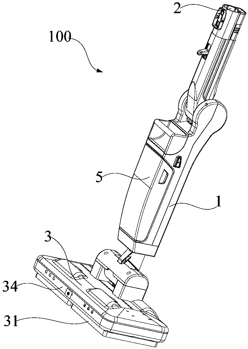
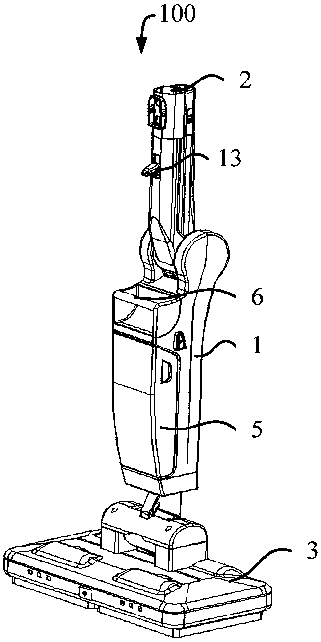
[0078] Refer below Figure 2 to Figure 35 A floor mopping device 100 according to some embodiments of the present invention is described.

[0079] According to some embodiments of the present inven...


PUM


Abstract

The invention provides a floor mopping device with a rotary limiting structure. The floor mopping device comprises a machine body, a floor mopping head assembly, a rotary connection part, a first limiting structure and a second limiting structure, wherein the machine body is provided with a first end, a second end and a shell body which extends between the first end and the second end; the floor mopping head assembly comprises a base which moves on a surface to be cleaned and a wiping element arranged at the bottom of the base; the rotary connection part is used for forming movable connectionbetween the base and the machine body, so that the machine body can rotate between a storage position and an utilization position; the first limiting structure is arranged on the rotary connection part and is used for preventing the machine body from being inclined frontward and/or rotating leftward and rightward at the storage position; the second limiting structure is arranged on the rotary connection part and is used for providing retention when the machine body is located at the storage position; when the machine body overcomes the retention, the machine body can be rotated to the utilization position, so that the gravity center of the floor mopping device at the storage position is stable and is at a vertical state all the time; a condition that a user picks up the fallen machine bodyfor a plurality of times through lowering self gravity center in a cleaning process is avoided, and the technical effects of optimizing a production connection structure and improving the user experience of the user are realized.

Description

technical field [0001] The invention relates to the technical field of cleaning equipment, in particular to a floor wiping device with a rotation limiting structure. Background technique [0002] Among the existing electric mops, such as figure 1 As shown, the tow bar 4' and the mopping head 2' are basically connected by the rotating shaft 6' and the fixed fulcrum, wherein the connecting end of the towing bar 4' is a single rotating shaft 6', and the connecting end of the mopping head 2' is set in line with the rotating shaft. 6' match the fixed fulcrum, the rotating shaft 6' rotates in the fixed fulcrum to realize the relative rotation between the mopping bar 4' and the mopping head 2', but there is no limit structure between the mopping head 2' and the mopping bar 4', when the user When the electric mop is not operated, the mop bar 4' will automatically rotate and fall under the action of its own gravity, so that the user must always hold the mop bar 4' to ensure that the...

Claims


Application Information

Patent Timeline
Patent Type & Authority Applications(China)
IPC IPC(8): A47L11/283A47L11/40
CPCA47L11/283A47L11/40A47L11/4038A47L11/4069
Inventor 吕冬祥倪兵兵
Owner JIANGSU MIDEA CLEANING APPLIANCES
Why Eureka
Try Eureka