

Method for double-cavity bladder clinical pressure measurement by silicon rubber catheter
A bladder and catheter technology, applied in the field of double-chamber bladder pressure measurement, can solve the problems of prostatic hyperplasia, such as difficulty in catheter placement, and achieve the effects of strong catheter compliance, wide sources, and simple manufacturing methods
Pending Publication Date: 2018-11-30
山西大医院
View PDF0 Cites 0 Cited by
- Summary
- Abstract
- Description
- Claims
- Application Information
AI Technical Summary
Problems solved by technology
[0003] The purpose of the present invention is to provide a silicone catheter for clinical pressure measurement method of double-chamber bladder, to further reduce the clinical application cost of urodynamic catheter, avoid the risk of hospital clinical infection, solve
Method used
View moreImage
Smart ImageViewing Examples

Examples
 PUM
 Abstract
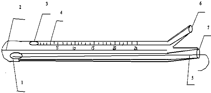
The invention discloses a method for double-cavity bladder clinical pressure measurement by a silicon rubber catheter. The method includes: after air is injected into a catheter balloon by an injectorthrough a check valve, cutting the balloon to expose a balloon port along the longitudinal axis direction of the catheter from a side hole of the balloon, cutting off the check valve of the silicon rubber catheter balloon to serve as a bladder pressure sensor connector, cutting off a urine collection bag connector of the silicon rubber catheter, disinfecting the urethral orifice, inserting the silicon rubber catheter into the urethra and the bladder, extracting a guide wire, linking a catheter bladder pressure sensor connector with a bladder pressure sensor connecting tube after drainage of residual urine, inserting a scalp needle connection seat into a perfusion pump tube connector to link with a perfusion pump tube, and performing cystometrography by the aid of a rectal balloon pressurecatheter. The method is simple and low in cost, convenience and feasibility in clinical catheterization are achieved, the success rate of catheterization of prostatic hyperplasia patients is increased by the guide wire in the catheter, the occurrence rate of urinary system infection caused by urodynamic examination and economic burden of the patients are reduced, and the method is especially suitable for clinical application.
Description
technical field [0001] The invention relates to a double-chamber bladder pressure measurement method, in particular to a method for clinical pressure measurement of a single-use double-chamber bladder with a silicone catheter. Background technique [0002] Urodynamic examination is a routine examination item in urology clinical work. The essence of urodynamic examination is an examination method for pathophysiological interpretation in the process of urine storage and excretion in the lower urinary tract. See "Wei Kun. About Laborie Urodynamic Analyzer Stability improvement of test urethral pressure[J].Medical Medical Equipment,2013,28(3):12-14."; Urodynamics is one of the important indicators to evaluate patients with voiding dysfunction, see "Negro C L, Muir G H. Chronic urinary retention in men: how we defineIt, and how does it affect treatment outcome[J].British Journal of Urology International,2012,110(11):1590-1594. ”and “Lewis JM, Yalla S V, Stanitski K E, et, al.Spe...
Claims
Login to View More Application Information
Patent Timeline
 IPC IPC(8): A61B5/20
CPCA61B5/205
Inventor张文瑾张利周艳何海燕王蓓张雁钢张姝
Owner山西大医院