
Puncture positioning device

A technology of positioning device and positioning rod, which is applied in the direction of puncture needles and trocars, etc. It can solve the problems of difficulty in grasping the angle accuracy and the inability of CT machine to dynamically observe the movement of puncture needles in real time, so as to improve the success rate and accuracy , avoid errors, and have a wide range of applications

Inactive Publication Date: 2018-11-30
杨会军 +1
View PDF0 Cites 2 Cited by
  • Summary
  • Abstract
  • Description
  • Claims
  • Application Information

AI Technical Summary

Problems solved by technology

[0002] In the prior art, in the process of puncture interventional therapy, since the CT machine cannot dynamically observe the movement of the puncture needle in real time, doctors mostly rely on memory or compare static images to subjectively judge the puncture angle. Therefore, it is difficult to grasp the accuracy of the angle

Method used


Image

  • Puncture positioning device
  • Puncture positioning device
  • Puncture positioning device

Examples


Embodiment Construction

[0037] Below in conjunction with specific embodiment, further illustrate the present invention. These examples are only for illustrating the present invention and are not intended to limit the scope of the present invention. In the description of the present invention, it should be noted that unless otherwise specified and limited, the terms "installation", "installation" and "connection" should be interpreted in a broad sense, for example, it can be a fixed connection or an optional connection. Detachable connection, or integral connection; it can be mechanical connection or electrical connection; it can be direct connection or indirect connection through an intermediary, and it can be the internal communication of two components. Those of ordinary skill in the art can understand the specific meanings of the above terms in the present invention in specific situations.

[0038] Now in conjunction with the accompanying drawings, the structural features of the present invention...


PUM


Abstract

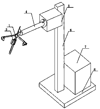
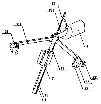
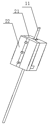
The invention discloses a puncture positioning device which comprises a guide rail and a puncture needle. The puncture needle is parallel to the guide rail, a clamping mechanism is slidably arranged on the guide rail and comprises a base and a cover plate, the cover plate covers the base, and a needle groove is formed in the top surface of the base along the length direction of the base in an embedded manner. The puncture positioning device has the advantages that needle penetration points, needle penetration angles and puncture distances can be determined by the aid of the puncture positioning device, accurate human interventional therapy can be carried out, errors due to the traditional experiential puncture can be prevented, accordingly, the surgical success rate can be increased, the surgical accuracy can be improved, and the puncture positioning device is convenient to use and high in efficiency and is safe.

Description

technical field [0001] The invention belongs to the technical field of medical device materials, and in particular relates to a puncture positioning device. Background technique [0002] In the prior art, during the puncture interventional treatment, since the CT machine cannot dynamically observe the movement of the puncture needle in real time, doctors mostly rely on memory or subjectively judge the puncture angle by comparing static images. Therefore, it is difficult to grasp the accuracy of the angle. Contents of the invention [0003] The purpose of the present invention is to provide a puncture positioning device, which can determine the needle entry point, needle entry angle and puncture distance, and perform precise interventional treatment on the human body, avoiding errors caused by traditional puncture based on experience, and improving the success rate and accuracy of the operation , Easy to use, safe and efficient. [0004] The present invention provides the ...

Claims


Application Information

Patent Timeline
IPC IPC(8): A61B17/34
CPCA61B17/3403
Inventor 杨会军高斌
Owner 杨会军
Learn More