
Purification apparatus and purification method combining spraying and photocatalytic degradation

A purification device and photocatalytic technology, applied in chemical instruments and methods, separation methods, gas treatment, etc., can solve the problems of poor degradation effect and high cost, and achieve the effect of improving degradation rate and degradation effect

Active Publication Date: 2018-11-30
四川蓝主角科技有限公司
View PDF5 Cites 1 Cited by
  • Summary
  • Abstract
  • Description
  • Claims
  • Application Information

AI Technical Summary

Problems solved by technology

[0006] The purpose of the present invention is to provide a purification device that combines spraying and photocatalytic degradation. The present invention solves the problems of high cost and poor degradation effect of existing purification devices

Method used


Image

  • Purification apparatus and purification method combining spraying and photocatalytic degradation

Examples


Embodiment 1

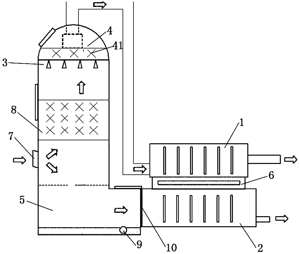
[0030] In practice, the spray system may include a communicable vessel, such as a spray tower. The spray tower is provided with a spray area 3 and a dehumidification area 4 for controlling the humidity of hydrophobic pollutants in the polluted gas, and the dehumidification area 4 is arranged above the spray area 3 . The spray area 3 is an area for spraying gas, in which a plurality of spray heads and other devices for spraying liquid can be arranged. The nozzle can be PP spiral nozzle, solid cone nozzle. In the dehumidification zone 4, defogging fillers 41 and the like can be installed. The defogging fillers 41 mainly collect water mist through contact with the fillers to condense on the filler surface to change the humidity. Changing the filler filling area can change the gas flow rate in a small range and increase the demist The mist filler can increase the contact area to facilitate dehumidification. The gas flow rate is mainly controlled by the fan (not shown in the sche...

Embodiment 2

[0044] As mentioned above, the purification method of polluting gas, after spraying the polluting gas with a spray system, dissolves the hydrophilic pollutants in the liquid phase and the hydrophobic pollutants that are still in the gaseous state, and converts the solution into a liquid phase The hydrophilic pollutants are passed into the liquid phase degradation unit 2 for photocatalytic degradation, and the hydrophobic pollutants which are still gaseous are passed into the gas phase degradation unit 1 for photocatalytic degradation.


PUM


Abstract

The invention discloses a purification apparatus combining spraying and photocatalytic degradation. The purification apparatus combining spraying and photocatalytic degradation comprises a spray system, a liquid phase degrading part and a gas phase degrading part; the spray system is used for dissolving hydrophilic pollutants of polluted air in liquid so as to separate hydrophilic pollutants fromhydrophobic pollutants; the liquid phase degrading part is used for receiving the hydrophilic pollutants from the spray system and performing degradation treatment on the hydrophilic pollutants; the gas phase degrading part is used for receiving the hydrophobic pollutants from the spray system and performing degradation treatment on the hydrophobic pollutants; photocatalytic materials are arrangedin both the liquid phase degrading part and the gas phase degrading part; a shared light source area is arranged between the liquid phase degrading part and the gas phase degrading part; and the light source area is used for providing light source needed by the liquid phase degrading part and the gas phase degrading part for performing degradation. By arranging degradation processes as two parts,including a liquid phase degradation part and a gas phase degradation part, the purification apparatus is capable of effectively improving volatile gas removal rate and removal effects.

Description

technical field [0001] The invention relates to the field of environmental protection, in particular to a purification device and a purification method combining spraying and photocatalytic degradation. Background technique [0002] With the continuous growth of my country's economy and the continuous improvement of the level of industrialization, the discharge of organic waste gas and wastewater is increasing, and the pollution of air and water resources is becoming more and more serious. Volatile organic compounds (VOCs) not only directly and seriously affect human health, but also form an important precursor of PM2.5, reducing air quality. The government has issued a number of VOCs pollution control policies and regulations, and environmental protection authorities at all levels have also listed VOCs as a key target for rectification. Organic wastewater can easily cause water eutrophication, poison aquatic animals and plants or accumulate in them, destroying the ecosyste...

Claims


Application Information

Patent Timeline
IPC IPC(8): B01D53/86B01D53/44
CPCB01D53/007B01D53/8687B01D2257/708
Inventor 彭文茂李化兰勇王早军刘桢
Owner 四川蓝主角科技有限公司
Learn More