Plate cutting device for production of fire-fighting barrel
A technology for cutting devices and fire buckets, applied in the direction of shearing devices, shearing machine accessories, metal processing equipment, etc., can solve the problems of poor stability of metal sheets, low reliability of use, and affecting cutting effects, so as to improve the cutting effect , Improve the reliability of use and the effect of improving stability
- Summary
- Abstract
- Description
- Claims
- Application Information
AI Technical Summary
Problems solved by technology
Method used
Image

Examples
Embodiment Construction
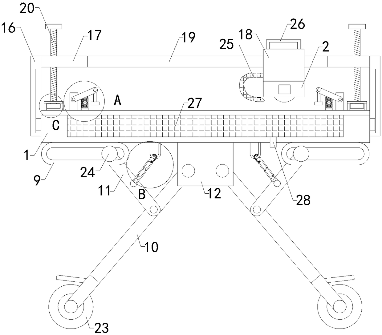
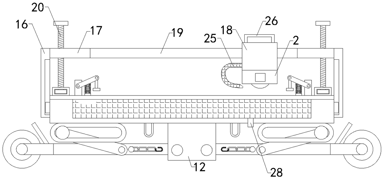
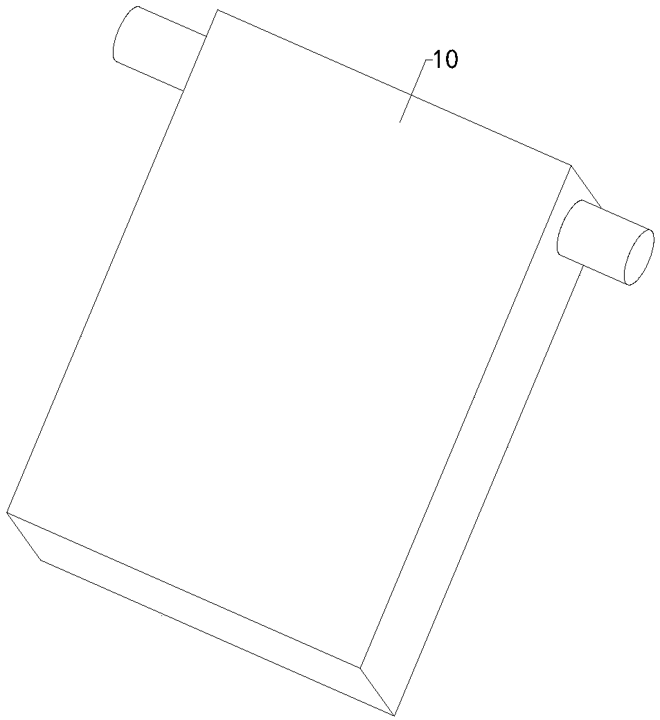
[0022] The specific implementation manners of the present invention will be further described in detail below in conjunction with the accompanying drawings and embodiments. The following examples are used to illustrate the present invention, but are not intended to limit the scope of the present invention.
[0023] Such as Figure 1 to Figure 8 As shown, a plate cutting device for production of fire buckets of the present invention includes a cutting table 1 on which a hand-held cutting machine 2 is placed; two groups of left fixed blocks 3, two groups of right fixed blocks, two groups of left-turning Bar 4, two groups of right turning rods, two groups of left compression springs 5, two groups of left reinforcement plates 6, two groups of right compression springs, two groups of right reinforcement plates, two groups of left compression rods 7, two groups of right compression rods, Two groups of left pressing plates 8 and two groups of right pressing plates, the bottom ends o...
PUM
 Abstract
Description
Claims
Application Information
PatSnap Eureka turns technology decisions into work you can execute. Powered by our Innovation Knowledge Graph, it runs expert workflows across engineering, life sciences, materials and intellectual property. Get your review-ready output in minutes.


