Pipe cutting machine tool

A pipe cutting and machinist technology, applied in the field of pipe cutting machine tooling, can solve the problems of high labor cost consumption, low efficiency, and low accuracy, and achieve the effect of avoiding personal safety risks and solving the effect of low manual operation efficiency

Active Publication Date: 2018-11-30
JIANGSU YAAO PRECISION MASCH CO LTD
View PDF13 Cites 0 Cited by
  • Summary
  • Abstract
  • Description
  • Claims
  • Application Information

AI Technical Summary

Problems solved by technology

[0003] In order to solve the above-mentioned technical problems, the present invention discloses a tooling for a pipe cu

Method used


Image

  • Pipe cutting machine tool
  • Pipe cutting machine tool
  • Pipe cutting machine tool

Examples


Embodiment Construction

[0025] Specific embodiments of the present invention will be described below in conjunction with the accompanying drawings.

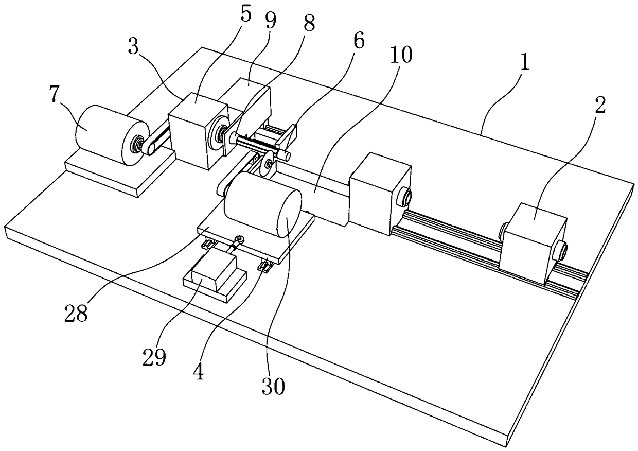
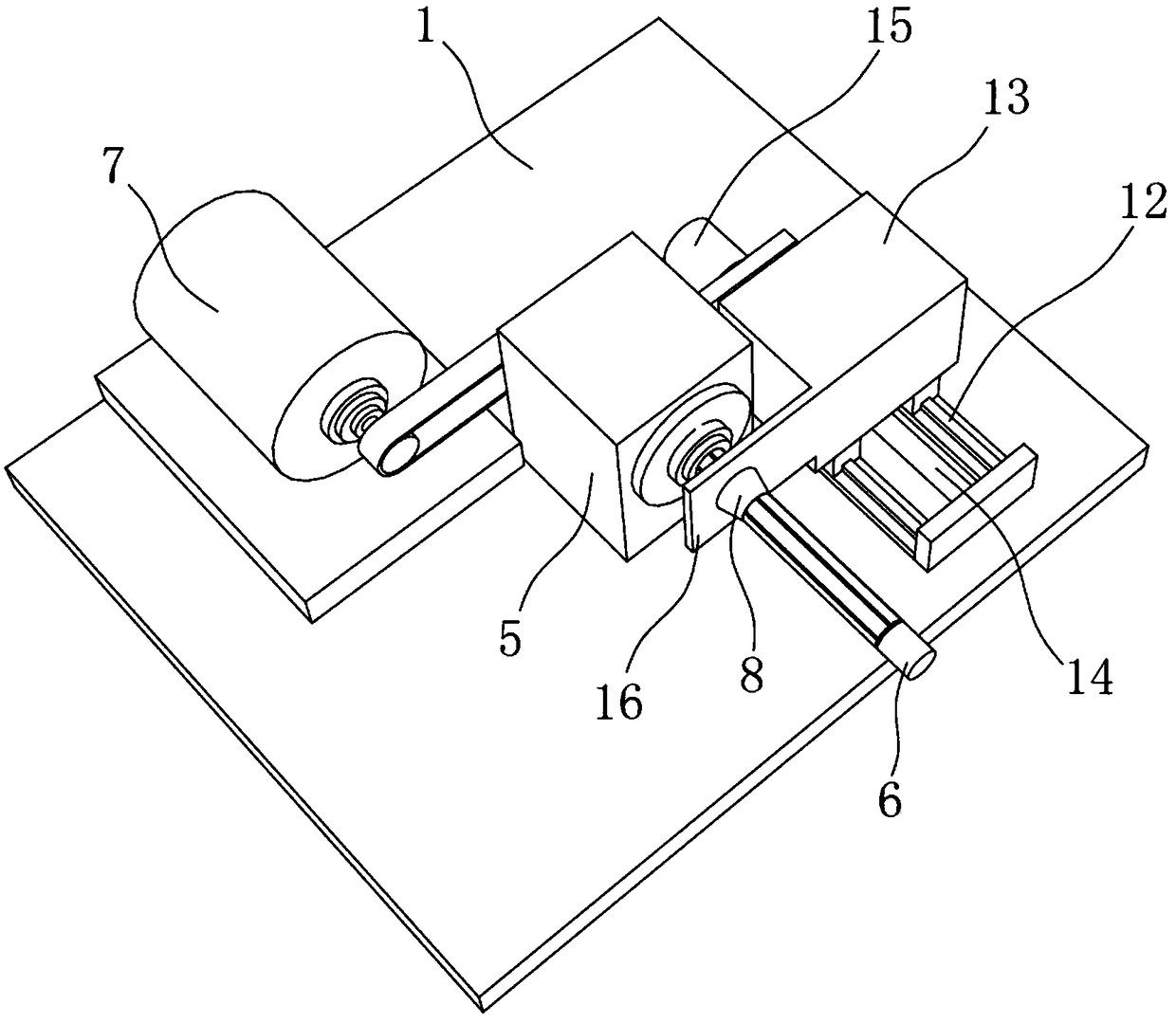
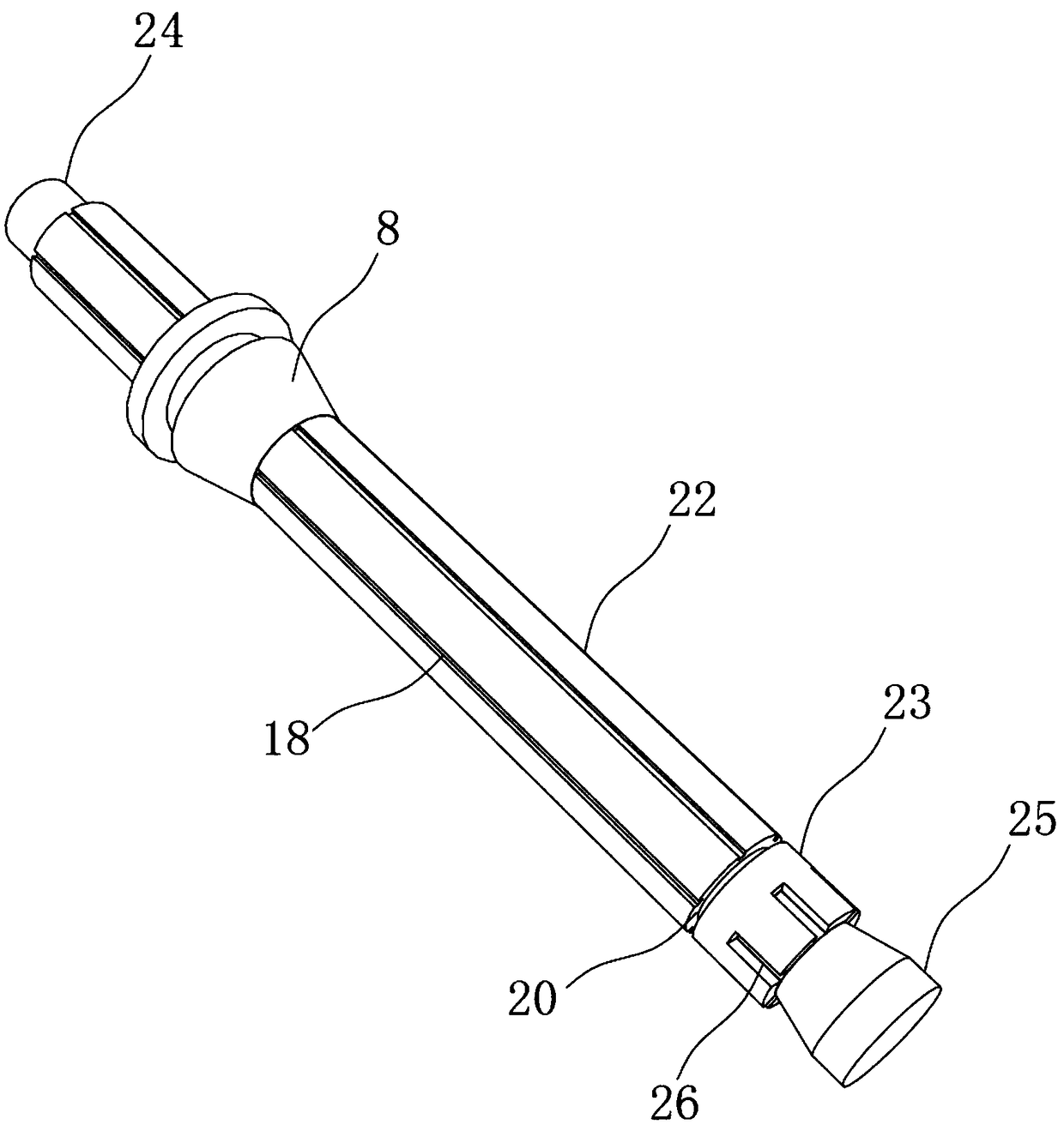
[0026] Such as Figure 1 to Figure 7 As shown, it is a pipe cutting machine tooling of this embodiment, including a workbench 1, on which a feeding device 2, a positioning device 3 corresponding to the feeding device 2, and a pipe cutting device 4 are arranged, and the feeding device 2 is arranged along the The axial movement of the pipe material, the positioning device 3 includes a fixed seat 5 arranged on the workbench 1, a positioning rod 6 rotating on the fixed seat 5, and a rotating motor 7 that drives the positioning rod 6 to rotate. The positioning rod 6 is arranged along the axial direction of the pipe , the diameter of the positioning rod 6 is smaller than the internal diameter of the pipe, and the positioning rod 6 is provided with a conical top block 8 that can match the internal diameter of the pipe, and the conical top block 8 slides on the...


PUM


Abstract

The invention provides a pipe cutting machine tool, and relates to metal cutting machining machines. The pipe cutting machine tool comprises a workbench provided with a feeding device, a positioning device and a pipe cutting device. The feeding device moves for feeding in the axial direction of a pipe. The positioning device comprises a fixing base arranged on the workbench, a positioning rod rotating on the fixing base, and a rotation motor driving the positioning rod to rotate. The positioning rod is arranged in the axial direction of the pipe. The diameter of the positioning rod is smallerthan the inner diameter of the pipe. The positioning rod is provided with a conical ejector block capable of being matched with the pipe in inner diameter. The conical ejector block slides on the positioning rod in the axial direction. The workbench is provided with a drive mechanism for driving the conical ejector block to slide. The position, located at the end portion of the positioning rod, ofthe workbench is provided with a through hole. A collecting device is arranged below the through hole. The pipe cutting device comprises a cutter arranged in the radial direction of the pipe. The cutter is arranged on the workbench in a sliding manner in the radial direction of the pipe. According to the pipe cutting machine tool, safety risks existing during manual operation are avoided, and theproblem that the manual operation efficiency is low is solved.

Description

technical field [0001] The invention relates to a metal cutting machine, in particular to a tooling for a pipe cutting machine. Background technique [0002] The pipes produced in industry are long. When used to make other corresponding products, the pipes need to be cut according to the required length. In the prior art, workers are required to control the machine, which is inefficient, high labor cost, and operators have personal safety. risk. Contents of the invention [0003] In order to solve the above-mentioned technical problems, the invention discloses a tooling for a pipe cutter, which solves the problems of high labor cost consumption, low accuracy and low efficiency in the prior art. [0004] The present invention adopts following technical scheme: [0005] A tooling for a pipe cutting machine, comprising a workbench, on which a feeding device, a positioning device corresponding to the feeding device, and a pipe cutting device are arranged, and the feeding dev...

Claims


Application Information

Patent Timeline
IPC IPC(8): B23Q7/00B23D21/00B23D33/02
CPCB23D21/00B23D33/02B23Q7/00
Inventor 方国祥
Owner JIANGSU YAAO PRECISION MASCH CO LTD
Why Eureka
Try Eureka