
Reaction tube grasping device and analyzer

A grasping device and reaction tube technology, which is applied in the direction of program control manipulators, manufacturing tools, chucks, etc., can solve the problems of damage to the analyzer instrument, shorten the service life of the instrument, damage the reaction tube, etc., so as to reduce the production and use costs, improve the Service life and effect of reducing the degree of wear

Active Publication Date: 2021-08-27
JINAN BIOBASE BIOTECH
View PDF4 Cites 0 Cited by
  • Summary
  • Abstract
  • Description
  • Claims
  • Application Information

AI Technical Summary

Problems solved by technology

[0004] In the working state of the chemiluminescence analyzer, the reaction tube grasping device switches between the grasping action and the placement action at high frequency, which further aggravates the degree of wear between the driving device and the gripper, and serious Affected the service life of the reaction tube gripping device
[0005] In the working state of the chemiluminescence analyzer, due to the influence of factors such as instrument movement and aging, the grasping device fails to operate, which will cause serious collisions to the grasping device, which will damage both the reaction tube and the matching analyzer instrument
[0006] Based on the above reasons, in the current reaction tube grabbing device, the degree of wear between the driving device and the grabbing device has become the most important failure factor in the reaction tube grabbing device, which seriously limits the reliability of the reaction tube grabbing device. and the grabbing device runs out of control and is easy to damage the instrument, reducing the service life of the instrument

Method used

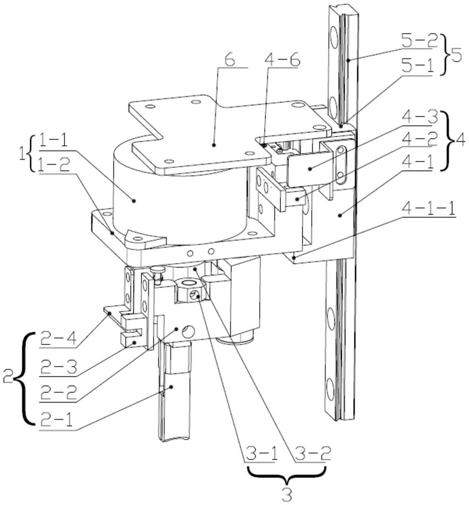
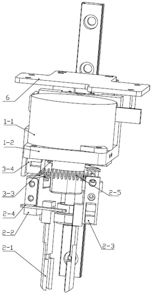
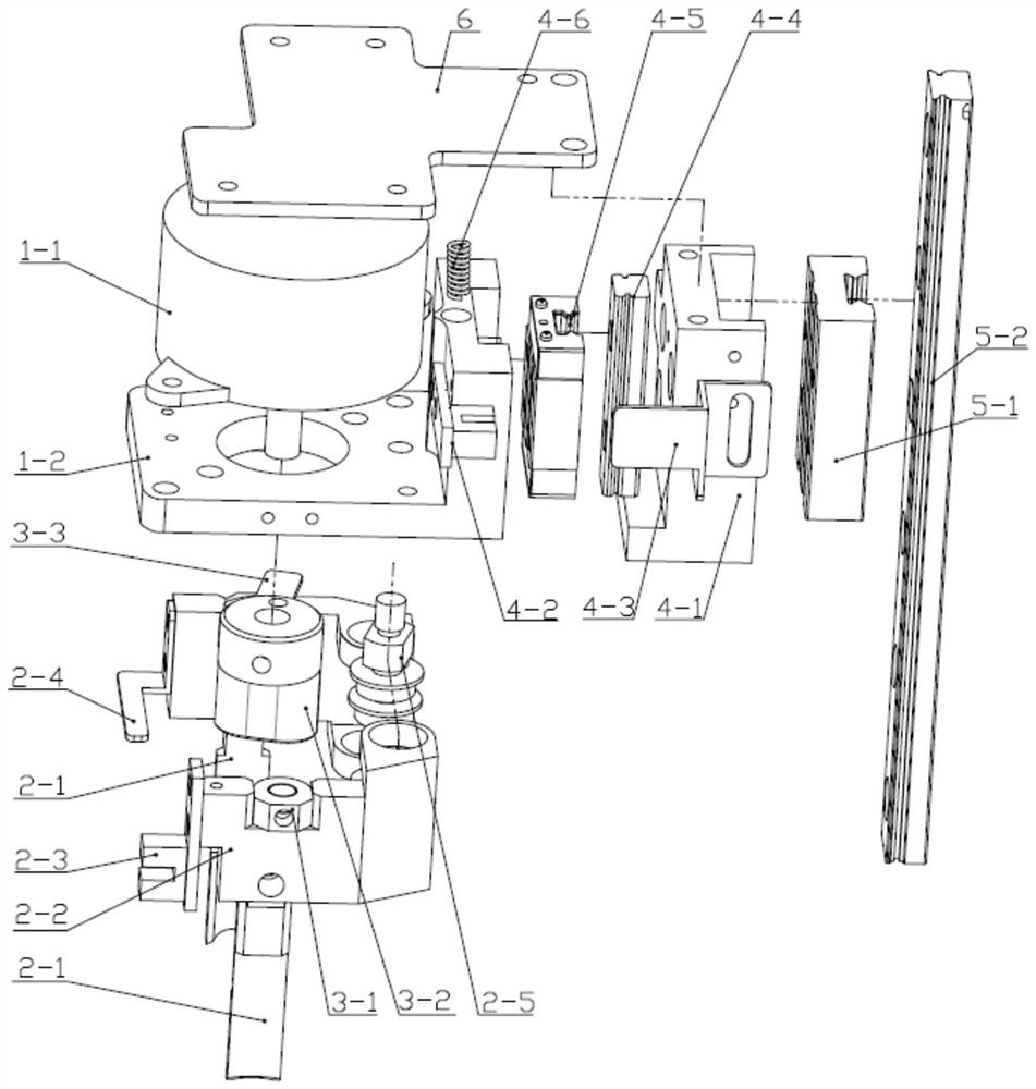

Image

  • Reaction tube grasping device and analyzer
  • Reaction tube grasping device and analyzer
  • Reaction tube grasping device and analyzer

Examples


Embodiment Construction

[0029] In order to make the technical problems, technical solutions and advantages to be solved by the present invention clearer, the following will describe in detail with reference to the drawings and specific embodiments.

[0030] On the one hand, the present invention provides a reaction tube grasping device, such as Figure 1 to Figure 3 As shown, it includes a clamping device 2 for clamping the reaction tube, a driving device 1 for driving the clamping device 2 and a sliding device 5 for connecting with the analyzer, and the driving device 1 and the clamping device 2 are arranged There is a wear-resistant device 3, and an anti-collision device 4 is arranged between the driving device 1 and the sliding device 5, wherein,

[0031] The wear-resistant device 3 includes a wear-resistant rotating block 3-2 fixedly connected to the driving device 1 and a wear-resistant fixed block 3-1 fixedly connected to the clamping device 2, the wear-resistant rotating block 3-2 and the wear...


PUM


Abstract

The invention discloses a reaction tube grasping device and an analyzer, and relates to the technical field of analyzer equipment. The reaction tube grasping device includes a clamping device, a driving device and a sliding device, a wear-resistant device is provided between the driving device and the clamping device, and an anti-collision device is provided between the driving device and the sliding device, so The wear-resistant device includes a wear-resistant rotating block fixedly connected with the driving device and a wear-resistant fixed block fixedly connected with the clamping device, the wear-resistant rotating block and the wear-resistant fixed block are in rolling friction fit, the The driving device controls the opening and closing of the clamping device by driving the rotation of the wear-resistant rotating block; the anti-collision device includes an anti-collision bracket elastically connected to the driving device, and the anti-collision bracket is fixedly connected to the sliding On the device, the anti-collision support and the driving device are respectively provided with a first photoelectric switch and a first photoelectric switch baffle that cooperate with each other. The invention can not only reduce wear, but also prevent serious collisions.

Description

technical field [0001] The invention relates to the technical field of analyzer equipment, in particular to a reaction tube grasping device and an analyzer. Background technique [0002] In current automatic chemiluminescence analyzers, automatic biochemical analyzers and other instruments, the reaction tube gripping device is mainly driven by an electromagnet or a motor. The reaction tube grasping device usually includes at least two grippers that cooperate with each other, and the electromagnet or motor drives each gripper to change the relative position between the grippers, thereby realizing the gripping of the reaction tube. , shift and place work. [0003] However, during actual use and further research and development, the inventors of the present application found that the structure of the current reaction tube grasping device is not reliable, and the main reasons are as follows: [0004] In the working state of the chemiluminescence analyzer, the reaction tube gra...

Claims


Application Information

Patent Timeline
Patent Type & Authority Patents(China)
IPC IPC(8): B25J9/12B25J9/00B25J15/12
CPCB25J9/00B25J9/12B25J15/12
Inventor 袁文虎郭宣城杨杰明张宾张谦黄晓凤
Owner JINAN BIOBASE BIOTECH
Learn More