
Open-cut station body structure and construction method thereof

A technology for the main structure and station, applied in the direction of basic structure engineering, underwater structures, artificial islands, etc., can solve the problems of reduced service life and poor flexibility of the shield machine, and achieve shortened construction period, simple construction, and strong operability Effect

Inactive Publication Date: 2018-11-30
BEIJING MUNICIPAL CONSTR
View PDF2 Cites 13 Cited by
  • Summary
  • Abstract
  • Description
  • Claims
  • Application Information

AI Technical Summary

Problems solved by technology

[0003] At present, the shield tunneling method used in open-cut stations makes the shield machine less flexible during construction, and its repeated disassembly, assembly, disassembly, dragging and passing stations greatly reduces the service life of the shield machine
At the same time, the additional construction costs caused by the construction of the shield launching shaft, receiving shaft, and U-turn shaft, as well as the dismantling, hoisting, and transition of the shield machine, make the project cost per km in the shield tunneling method relatively high. The cost of normal propulsion of the machine increases by nearly 10%; and for the dragging of the shield machine to pass the station, it involves the additional cost of deepening and widening the station, which increases by about 6% to 8% per km

Method used


Image

  • Open-cut station body structure and construction method thereof
  • Open-cut station body structure and construction method thereof
  • Open-cut station body structure and construction method thereof

Examples


Embodiment Construction

[0033] The technical solutions of the present invention will be further described below in conjunction with the accompanying drawings and specific embodiments.

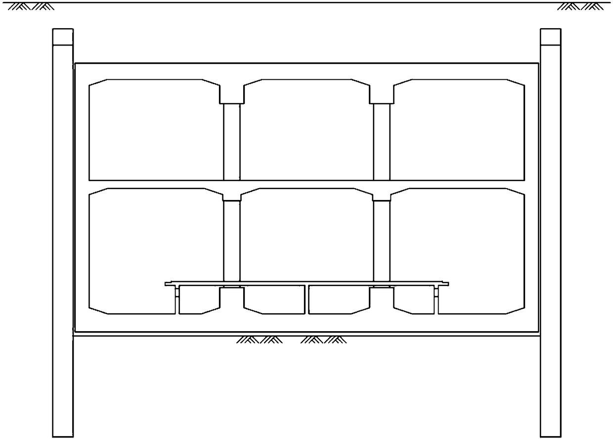
[0034] see figure 1 , a main structure of an open cut station. The main body of the station is a two-story, double-column, three-span box structure. The station is equipped with 3 entrances and exits, 1 safety entrance and 2 groups of wind pavilions. There are 3 entrances and exits on the south side of the station; No. 1 wind kiosk is located at the top of one end of the station, and No. 2 wind kiosk is set on the side of the other end of the station, hanging on the main body of the station; No. 1 safety entrance is located on the side of the station.

[0035] Taking the total length of the station as 285.75m, the effective platform center mileage right BK5+453.000, and the rail surface elevation at the effective platform center of the station as 27.970m as an example: the station is an open-cut double-layer and three...


PUM


Abstract

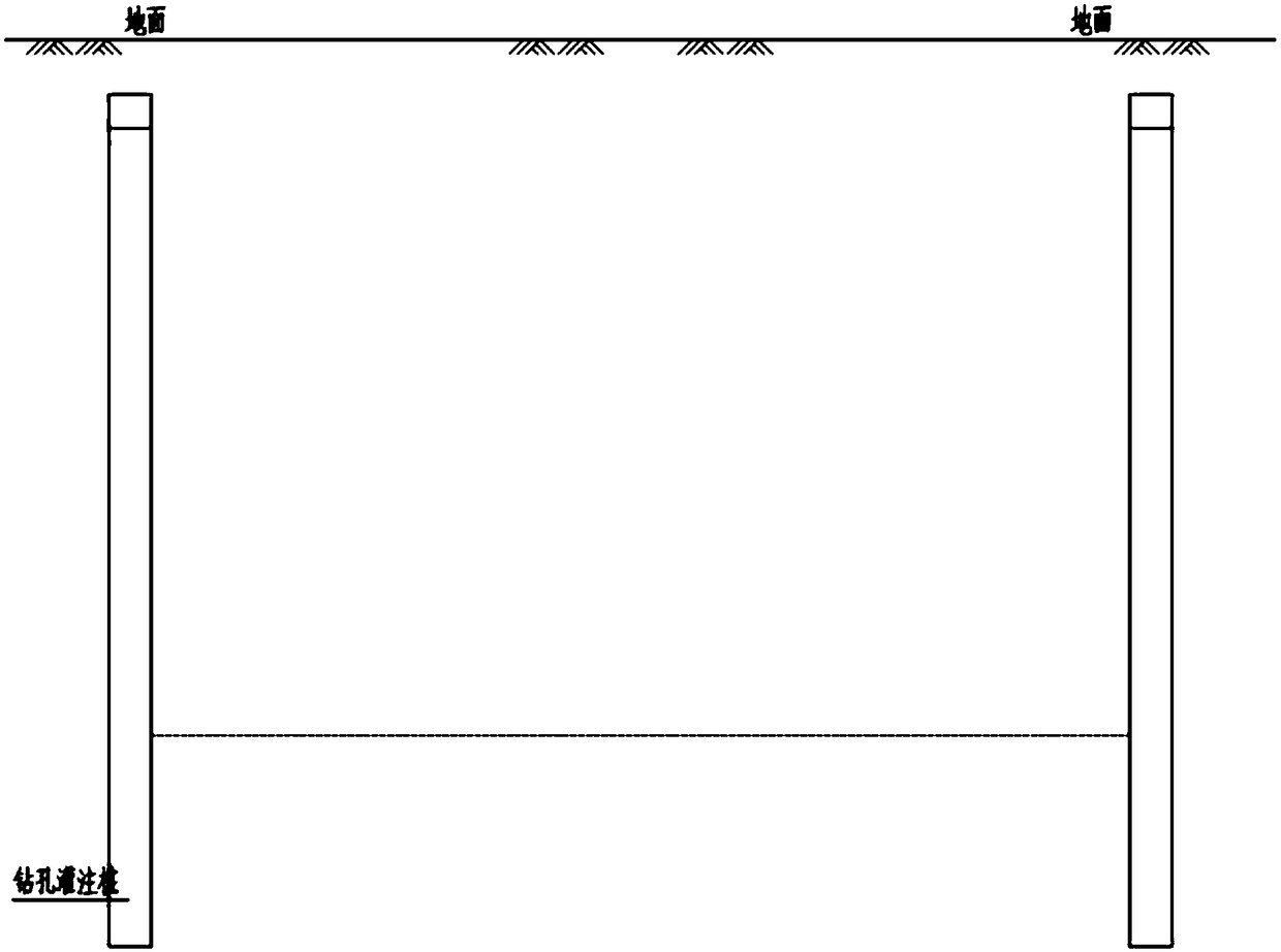
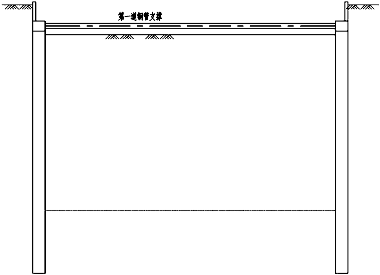
The invention discloses an open-cut station body structure and a construction method thereof. A station body is of a two-layer double-column three-span box-shaped structure. The construction method includes the steps that a site is leveled, a precipitation well is dug, precipitation is carried out, foundation pit drainage measures are taken, and cast-in-situ bored piles are arranged; a foundationpit is dug to the depth 0.7 m below a first support, pile top crown beams are arranged, and the first steel support is erected; the foundation pit continues to be dug downwards to the bottom of the foundation pit, a second support and a third support are sequentially erected, and waist rails are put in time; a bottom plate concrete structure is poured, side wall waterproof layers are arranged, andpart of side walls are poured; inverted supports are arranged, the third steel support is detached, and a remaining side wall structure on the second floor underground and a middle plate structure onthe first floor underground are poured; and the second steel support is detached, a side wall and top plate structure on the first layer underground is poured, a top plate waterproof layer is arranged, timely backfill is carried out, backfill is carried out to the position of the first steel support, the first steel support and the inverted supports are detached after a soil layer is compacted, backfill is carried out to the ground, and a station plate structure and other internal components are arranged.

Description

technical field [0001] The invention relates to the technical field of subway engineering structures, more specifically, it relates to a main structure of an open-cut station and a construction method thereof. Background technique [0002] With the rapid development of subway construction in major domestic cities, subway travel has become one of the most important daily transportation options in the city, and with the continuous development of the domestic economy, the construction of underground rail transit in many cities is currently in full swing. Both the subway and the urban comprehensive pipe gallery are laid along the main roads of the city; the construction of the subway also needs to adapt to various geological conditions, and at the same time, the complex underground environment poses a severe test to the durability of the subway structure. [0003] At present, the shield tunneling method used in open-cut stations makes the shield machine less flexible during cons...

Claims


Application Information

Patent Timeline
Patent Type & Authority Applications(China)
IPC IPC(8): E02D29/045
CPCE02D29/04E02D29/045
Inventor 孟庆龙张永恒赵晨阳高健张永生杨广钊赵艳双常国栋赵成杨佳
Owner BEIJING MUNICIPAL CONSTR
Learn More