Device for controlling pouring height of concrete at lower end of framework, and using method thereof

A concrete and frame technology, applied in building construction, building material processing, building type, etc., can solve problems such as difficulty in controlling the elevation of the upper surface of concrete, increasing the strength and stiffness of the root of the frame, and affecting the removal of accumulated water in the frame, etc. To achieve the effect of easy control of depth, extended service life and convenient installation

Pending Publication Date: 2018-11-30
NORTHWEST ELECTRIC POWER DESIGN INST OF CHINA POWER ENG CONSULTING GROUP
View PDF6 Cites 0 Cited by
  • Summary
  • Abstract
  • Description
  • Claims
  • Application Information

AI Technical Summary

Problems solved by technology

[0004] Since the concrete is located inside the lower end of the frame, the elevation of the upper surface of the poured concrete is not easy to control when pouring the concrete
The elevation of the upper surface of the poured concrete is too low, indicating that the amount of concrete poured into the steel pipe at the lower end of the frame is small, and the purpose of increasing the strength and stiffness of the frame root cannot be achieved; the elevation of the upper surface of the poured concrete is too high, indicating that the concrete is poured into the steel pipe at the lower end of the frame If the amount is too large, it will block the drainage holes of the frame, affect the removal of accumulated water inside the frame, cause corrosion of the frame, and reduce the service life of the frame

Method used


Image

  • Device for controlling pouring height of concrete at lower end of framework, and using method thereof
  • Device for controlling pouring height of concrete at lower end of framework, and using method thereof
  • Device for controlling pouring height of concrete at lower end of framework, and using method thereof

Examples


Embodiment Construction

[0023] In order to more clearly illustrate the technical means and creative features of the implementation of the present invention, the present invention will be further elaborated below in conjunction with the accompanying drawings.

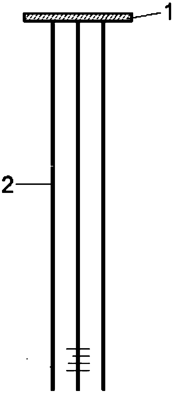
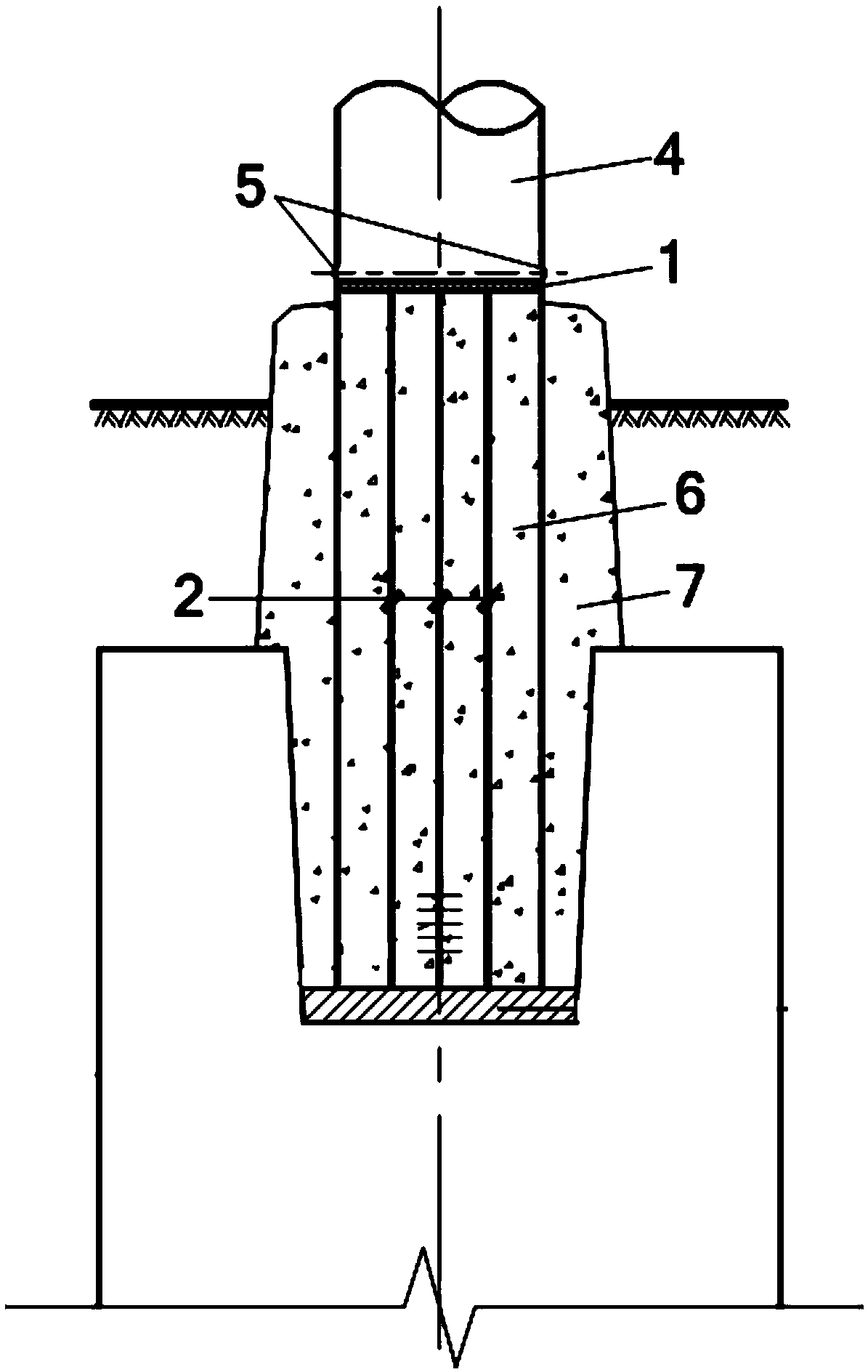
[0024] Such as figure 1 As shown, a device for controlling the pouring height of concrete in the steel pipe at the root of the frame includes a grout plate 1 and a positioning steel bar 2 .

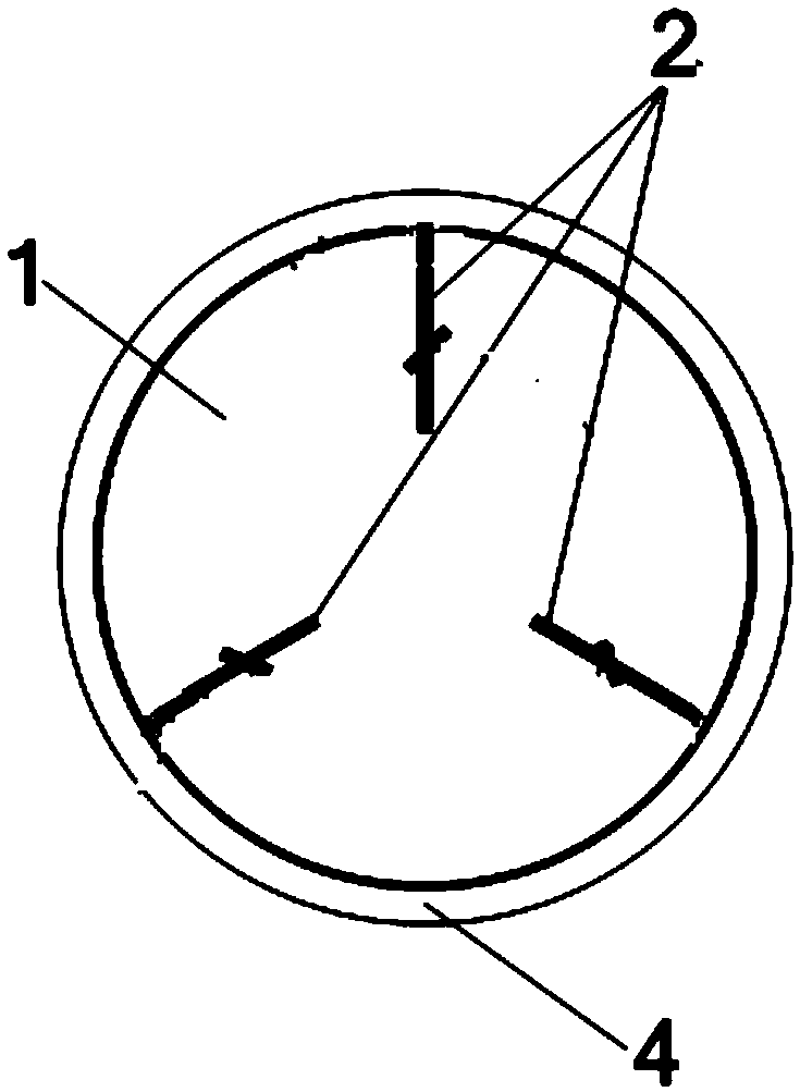
[0025] Wherein, the baffle plate 1 is in the shape of a disk, and its diameter matches the inner diameter of the frame 4. The bottom surface of the baffle plate 1 is vertically and fixedly connected with a plurality of positioning steel bars 2, and the circumference of the multiple positioning steel bars 2 are evenly distributed on the wall of the baffle plate 1. on and at the edge of the baffle 1.

[0026] The length of the positioning stiffener 2 is equal to the distance from the lower end of the frame 4 to the surface elevation.

[0027] The number of...


PUM


Abstract

The invention discloses a device for controlling the pouring height of concrete at the lower end of a framework. A slurry baffle is fixed to the interior of the lower end of the framework in a weldedmode through a positioning steel bar. The upper surface of the slurry baffle is flush with the lower edge of a drainage hole located in the pipe wall of the framework. After the position of the slurrybaffle is fixed well, the concrete is poured at the position, below the slurry baffle, of the lower end of the framework firstly, then the lower end of the framework is inserted into a hole of a foundation, and the concrete is poured in the base cup opening. The device is easy to manufacture and convenient to use, the position of the slurry baffle in a steel pipe is controlled easily, rusting anddamage of the interior of the root of the framework due to water accumulating can be effectively prevented, and the service life of the framework is prolonged.

Description

【Technical field】 [0001] The invention belongs to the field of substation frame design, in particular to a device for controlling the pouring height of concrete in a steel pipe at the root of the frame. 【Background technique】 [0002] The frame is the focus and difficulty of substation civil engineering design. With the acceleration of the construction of power transmission and transformation projects in my country, higher requirements are put forward for the structural design of power transformation structures. Not only the strength and stability requirements of the structure itself must be considered, but also the cost and lightness of appearance should be considered. [0003] Since the frame is often made of steel, it needs to be processed in the steel structure processing plant in advance and then transported to the site for hoisting; in order not to affect the installation period, the civil construction unit will pour the foundation of the frame before the frame arrives...

Claims


Application Information

Patent Timeline
Patent Type & Authority Applications(China)
IPC IPC(8): E04G21/10E04H12/22
CPCE04G21/10E04H12/2215
Inventor 李毅张玉明王宁壁顾群应捷贾鹏申卫华
Owner NORTHWEST ELECTRIC POWER DESIGN INST OF CHINA POWER ENG CONSULTING GROUP
Why Eureka
Try Eureka