Flexible led filament lamp
A technology of LED filament lamp and LED filament, which is applied to lighting auxiliary devices, lighting and heating equipment, light sources, etc. Effect
- Summary
- Abstract
- Description
- Claims
- Application Information
AI Technical Summary
Problems solved by technology
Method used
Image
Examples
Embodiment 1
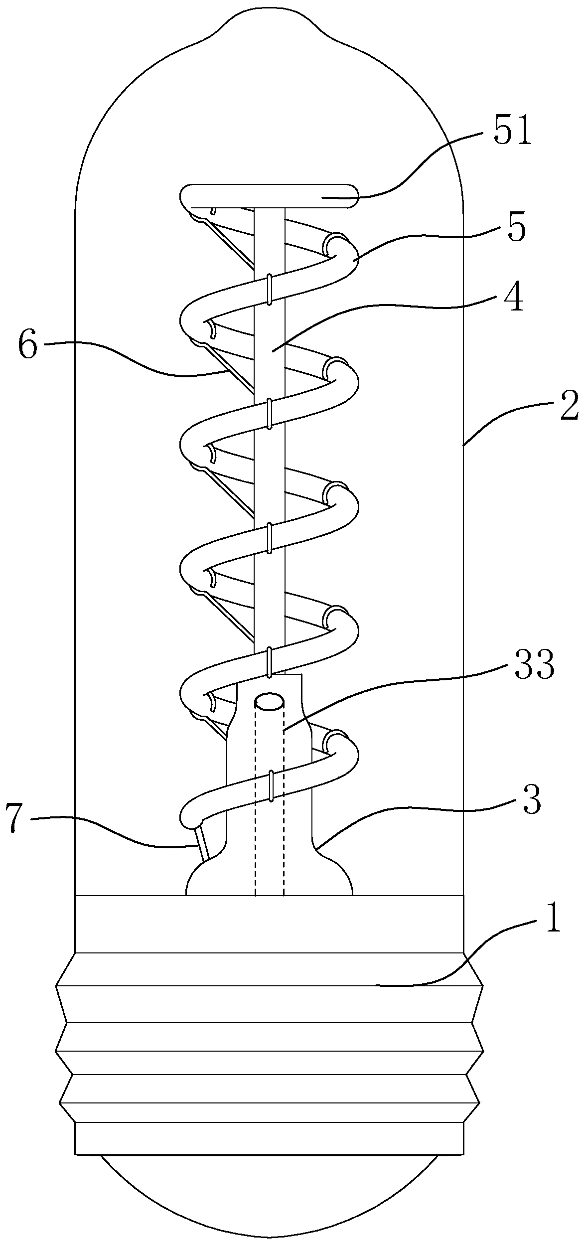
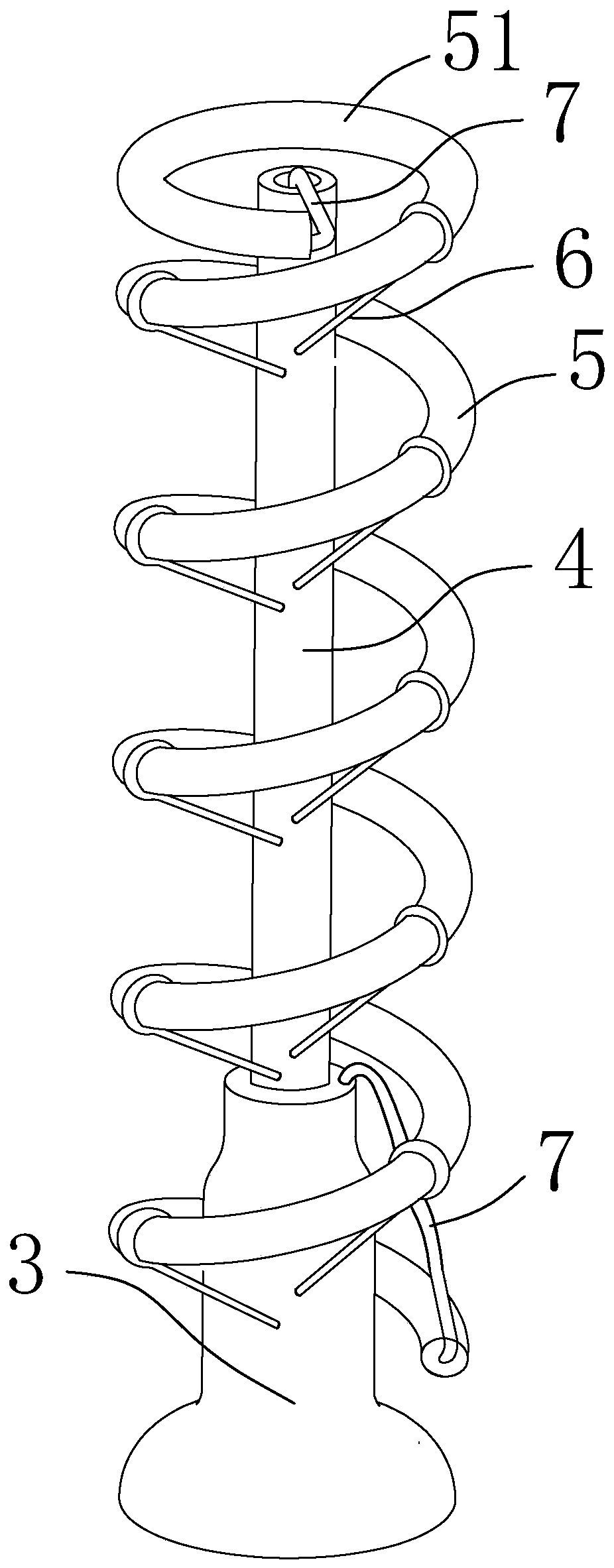
[0056] like figure 1 As shown, this embodiment includes an electroplating lamp cap 1 , a bulb 2 , a horn tube 3 , a stem 4 , an LED filament 5 and a support member 6 , and the electroplating lamp cap 1 is provided with an LED driver electrically connected to the electroplating lamp cap 1 .
[0057] The bottom end of the bulb shell 2 is fixed to the electroplating lamp cap 1, the main body shape of the bulb shell 2 is cylindrical, and the top is an arc surface.
[0058] The horn tube 3 is arranged in the bulb 2, the bottom of the horn tube 3 is fixed to the bottom of the bulb 2 to form a closed cavity in the bulb 2, and the horn tube 3 is provided with an exhaust pipe 33.
[0059] The stem 4 is located in the airtight cavity, and is vertically fixed on the top of the horn tube 3 , the stem 4 is hollow and communicates with the inside of the horn tube 3 .
[0060] The flexible LED filament 5 spirally surrounds the stem 4 and the outside of the trumpet tube 3, so that the entire...
Embodiment 2
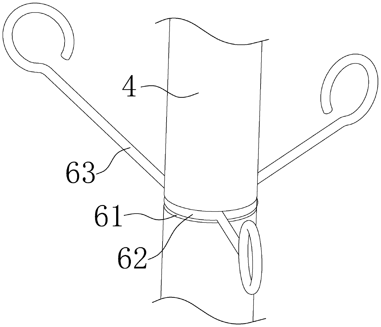
[0065] The difference between this embodiment and Embodiment 1 lies in the structure of the support member 6 .
[0066] like image 3 As shown, in this embodiment, the outer surfaces of the stem 4 and the trumpet tube 3 are provided with an annular groove 61, and the support member 6 includes a fixing ring 62 sleeved in the annular groove 61, and a plurality of one ends are fixed to the fixing ring 62. , the other end is bent into a short metal wire 63 in the shape of a hanging ring, and the hanging ring part of the short metal wire 63 is socketed with the LED filament 5; in this embodiment, according to the shape of the spiral LED filament 5, each fixing ring 62 is provided with Three short wires 63 . The short metal wire 63 can freely bend the hanging ring to hook the key parts of the LED filament 5, and fix the LED filament 5; the short metal wire 63 can also swing up and down, left and right, so as to adjust the position of the hanging ring to match the LED filament 5 in ...
Embodiment 3
[0068] The difference between this embodiment and Embodiment 1 lies in the structure of the support member 6 .
[0069] like Figure 4 As shown, in this embodiment, the support member 6 is a long metal wire 64, the middle part of the long metal wire 64 is wound around the stem 4 or the trumpet tube 3 at least one turn, and both ends of the long metal wire 64 are bent into a hanging ring shape And be connected with LED filament 5. It is more convenient to connect and fix through the long metal wire 64. After the long metal wire 64 is wound and tightened, the fastening effect on the LED filament 5 is better. Sliding up and down or falling off; and the whole supporting member 6 is composed of a long metal wire 64, which is convenient for replacement and length adjustment, so as to adapt to LED filaments 5 of different shapes.
[0070] In this embodiment, due to the connection characteristics of the long metal wire 64, there is no need to provide an annular groove 61 on the stem...
PUM
| Property | Measurement | Unit |
|---|---|---|
| angle | aaaaa | aaaaa |
Abstract
Description
Claims
Application Information
 - R&D
- Intellectual Property
- Life Sciences
- Materials
- Tech Scout
- Unparalleled Data Quality
- Higher Quality Content
- 60% Fewer Hallucinations
Browse by: Latest US Patents, China's latest patents, Technical Efficacy Thesaurus, Application Domain, Technology Topic, Popular Technical Reports.
© 2025 PatSnap. All rights reserved.Legal|Privacy policy|Modern Slavery Act Transparency Statement|Sitemap|About US| Contact US: help@patsnap.com


