Vertical movement lamp control main machine and vertical movement lamp group control system

A technology for controlling hosts and moving lights, applied in the direction of use feedback control, lighting and heating equipment, lighting device components, etc., can solve problems such as the inability to achieve multiple changing effects, improve flexibility, reduce wear and cost effect

Pending Publication Date: 2018-11-30
唐异武
View PDF0 Cites 1 Cited by
  • Summary
  • Abstract
  • Description
  • Claims
  • Application Information

AI Technical Summary

Problems solved by technology

In order to achieve a good decorative effect, traditional lamps can achieve changing effects of color, flashing frequency, and on and of

Method used


Image

  • Vertical movement lamp control main machine and vertical movement lamp group control system
  • Vertical movement lamp control main machine and vertical movement lamp group control system
  • Vertical movement lamp control main machine and vertical movement lamp group control system

Examples


Example Embodiment

[0028] The following combination Figure 1 to Figure 5 The specific embodiment of the present invention is further elaborated:

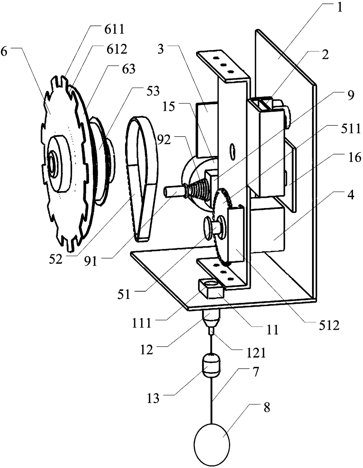
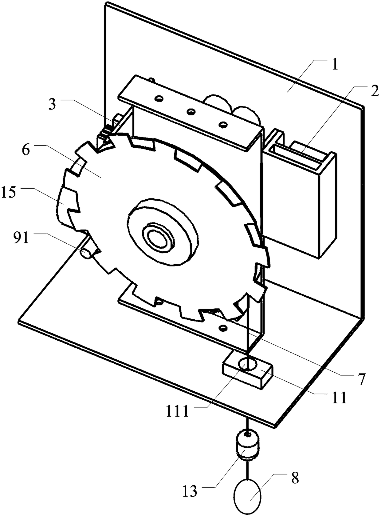
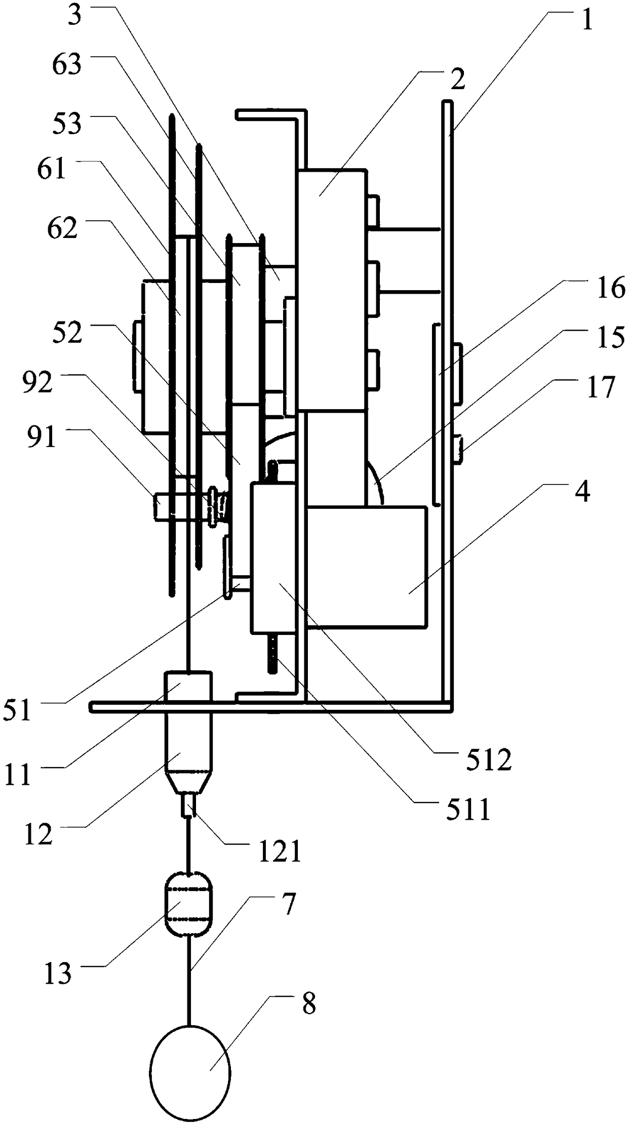
[0029] A control host for vertically moving lamps, comprising a chassis 1, a power module 2, a main control module 3 and a motor 4 are arranged inside the chassis 1, the power module 2 provides electric energy for the main control module 3 and the motor 4, and the main control module 3 controls the motor 4 rotation state;

[0030] The rotating shaft of the motor 4 is connected with a small synchronous wheel 51, and the small synchronous wheel 51 is connected with the large synchronous wheel 53 through a synchronous belt 52, so even a motor with a small power can output a large torque, which can drive the lifting of the heavier lamp 8 The large synchronous wheel 53 is coaxially connected with the winding reel 6, one end of the suspension wire 7 is wound on the winding reel 6, and the other end passes through the wire hole provided at the bottom of th...


PUM


Abstract

The invention relates to the technical field of lamplight control, in particular to a vertical movement lamp control main machine and a vertical movement lamp group control system. The main machine comprises a machine case, a power module, a master control module and a motor are arranged inside the machine case, the power module provides electric energy for the master control module and the motor,and the master control module controls the rotating state of the motor; a small synchronizing wheel is connected to a rotating shaft of the motor and is connected with a large synchronizing wheel through a synchronizing belt, the large synchronizing wheel is coaxially connected with a wire reel, one end of a suspension line is wound around the wire reel, and the other end of the suspension line penetrates a wire hole formed in the bottom of the machine case to be connected with a lamp; an acrylic suspending line guide block is arranged at the position, corresponding to the wire hole, of the inner side of the bottom of the machine case, a through hole in an inverted cone shape is formed in the upper surface of the acrylic suspending line guide block, the suspension line penetrates the through hole to be connected with the lamp, and excursion of the lamp in the horizontal direction can be avoided. According to the scheme, the lamp can be lifted and moved in the vertical direction, and the problem that decorative lamps can only be statically displayed in the past is solved.

Description

technical field [0001] The invention relates to the technical field of lighting control, in particular to a control host for vertically moving lights and a control system for vertically moving light groups. Background technique [0002] In addition to being used for daily lighting, today's lamps and lanterns also have an important purpose of decorating space. In order to achieve a good decorative effect, traditional lamps can achieve changing effects of color, flashing frequency, and on and off. However, these changing effects are generally only produced by stationary lamps, so other various changing effects cannot be realized. Contents of the invention [0003] Based on this, it is necessary to address the above technical problems and provide a control host for vertically moving lamps and a control system for vertically moving lamp groups, so that the lamps can move within a spatial range. [0004] A control host for vertically moving lamps, including a chassis, a power ...

Claims


Application Information

Patent Timeline
IPC IPC(8): F21V21/36F21V15/04F21V29/74F21V29/83G05D3/20
CPCF21V21/36F21V15/04F21V29/74F21V29/83G05D3/20
Inventor 唐异武
Owner 唐异武
Why Eureka
Try Eureka