Aircraft position determination method based on motion recovery structure

A technology for motion recovery structure and determination method, applied in the field of aerospace, can solve problems such as accumulated errors, difficult installation and use, and expensive precision instruments

Active Publication Date: 2018-11-30
中国人民解放军63920部队
View PDF1 Cites 9 Cited by
  • Summary
  • Abstract
  • Description
  • Claims
  • Application Information

AI Technical Summary

Problems solved by technology

There are the following disadvantages: using integral calculations to determine the pose, there is a problem of accumulating errors, especially in long-term applications, the accumulation of errors is large, and it is often necessary to use other accurate positioning methods to correct the calculation results of inertial navigation
There are the following disadvantages: because GPS satellite signals are provided by foreign navigation satellites, high-precision data are usually not available, so the accuracy of calculation results is poor, and whether the signals can be obtained normally is also subject to people; because the reception of GPS satellite signals is limited by the "line of sight" of satellites in orbit Due to the influence of occlusion, the accuracy and update frequency of the position information calculated by the GPS navigation method will decrease
There are the following disadvantages: the laser altimeter is a special equipment with high energy consumption, and this kind of precision instrument is expensive and difficult to install and use on general aircraft. This kind of one-dimensional matching navigation is suitable for flying in hilly terrain

Method used


Image

  • Aircraft position determination method based on motion recovery structure
  • Aircraft position determination method based on motion recovery structure
  • Aircraft position determination method based on motion recovery structure

Examples


Embodiment Construction

[0039] The specific embodiments of the present invention will be described in detail below with reference to the accompanying drawings, but it should be understood that the protection scope of the present invention is not limited by the specific embodiments.

[0040] Unless expressly stated otherwise, throughout the specification and claims, the term "comprising" or its conjugations such as "comprising" or "comprising" and the like will be understood to include the stated elements or components, and Other elements or other components are not excluded.

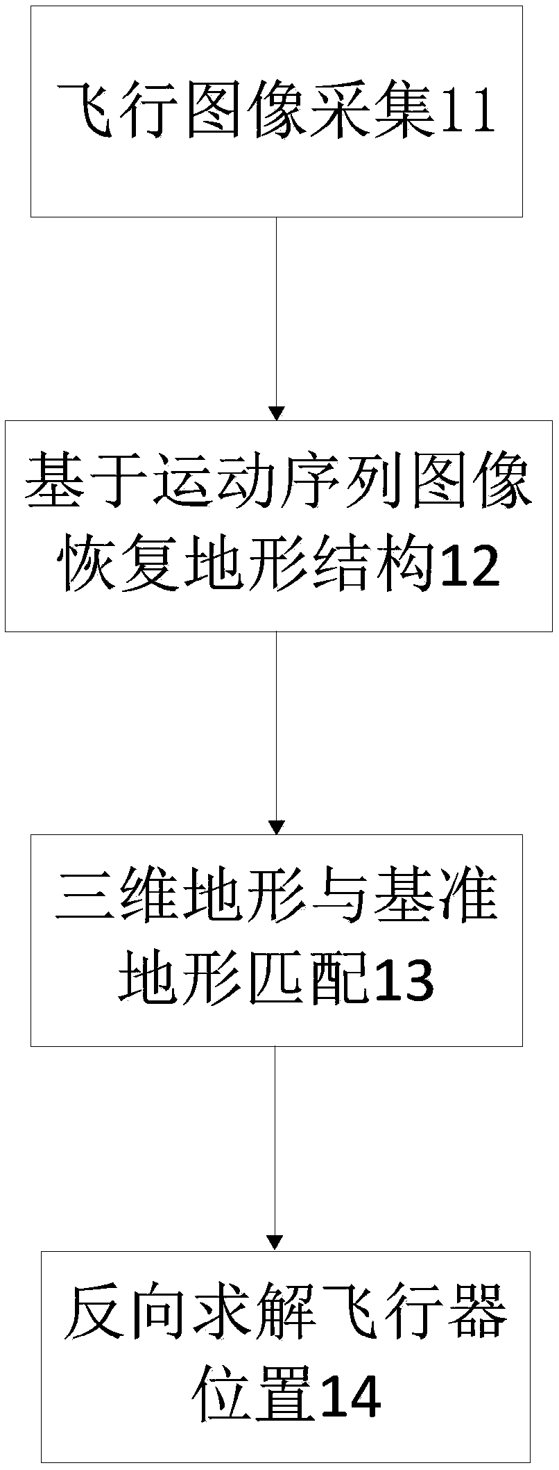
[0041] The basic principle of the aircraft position determination method based on the recovery structure from motion is to use the imaging sensor mounted on the aircraft to continuously image the terrain under the track during the flight, and form multi-view imaging of multiple positions for each area. The multi-view geometry principle uses the method of recovering the 3D structure of the scene from the motion camera in compute...


PUM


Abstract

The invention discloses an aircraft position determination method based on a motion recovery structure. The method is characterized in that an imaging device is used to continuously image the terrainunder a track to obtain a motion sequence image; and then a real-time three-dimensional topographic map is restored based on the motion sequence image and spatial three-dimensional coordinates of thepoints on the real-time three-dimensional topographic map under an attitude coordinate system of an aircraft body are obtained. The spatial three-dimensional coordinates of the points on the real-timethree-dimensional topographic map under the attitude coordinate system of the aircraft body are transformed to a parallel coordinate system of the aircraft. The spatial three-dimensional coordinatesof the points on the real-time three-dimensional topographic map under the parallel coordinate system of the aircraft can be converted to a ground reference terrain coordinate system, and finally theposition of the aircraft under the ground reference terrain coordinate system is solved inversely. The aircraft position determination method can accurately measure the position of the aircraft at lowcost and low energy consumption.

Description

technical field [0001] The invention relates to the field of aerospace technology, in particular to a method for determining the position of an aircraft based on a structure recovered from motion. Background technique [0002] In the process of navigation and control of aircraft such as spacecraft and UAVs, the position and attitude of the aircraft are the key information for safe flight and mission execution. Commonly used methods for determining the flight position and attitude of aircraft include inertial navigation, GPS-based navigation, and laser terrain measurement and scene matching navigation. [0003] The inertial navigation method uses navigation sensors such as accelerometers and gyroscopes to measure motion information. This method uses the real-time acceleration measurement of the accelerometer and performs integral operations to obtain the position and attitude information during flight. There are the following shortcomings: the use of integral operation to de...

Claims


Application Information

Patent Timeline
Patent Type & Authority Applications(China)
IPC IPC(8): G01C21/16G01C21/20G01C21/24
CPCG01C21/165G01C21/20G01C21/24
Inventor 李立春孙军苗毅于天一程肖范文山许颖慧冯晓萌袁春强
Owner 中国人民解放军63920部队
Why Eureka
Try Eureka