
Weighing device and method based on modal frequency of cantilever beam

A modal frequency, weighing device technology, applied in measurement devices, weighing, radiation weighing instruments, etc., can solve problems such as failure to meet detection requirements and detection errors

Pending Publication Date: 2018-11-30
FUZHOU UNIV
View PDF0 Cites 6 Cited by
  • Summary
  • Abstract
  • Description
  • Claims
  • Application Information

AI Technical Summary

Problems solved by technology

In the vibration detection and modal analysis of light thin-walled structural parts, the impact of the additional mass introduced by traditional contact sensors such as displacement and acceleration on the test piece cannot be ignored, which will cause a large error in detection, and for some surfaces Where processing quality is high and non-contact vibration testing is required, traditional vibration sensors cannot meet the detection requirements.

Method used


Image

  • Weighing device and method based on modal frequency of cantilever beam
  • Weighing device and method based on modal frequency of cantilever beam
  • Weighing device and method based on modal frequency of cantilever beam

Examples


Embodiment Construction

[0061] The present invention will be further described below in conjunction with the accompanying drawings and embodiments.

[0062] It should be pointed out that the following detailed description is exemplary and is intended to provide further explanation to the present application. Unless defined otherwise, all technical and scientific terms used herein have the same meaning as commonly understood by one of ordinary skill in the art to which this application belongs.

[0063] It should be noted that the terminology used here is only for describing specific implementations, and is not intended to limit the exemplary implementations according to the present application. As used herein, unless the context clearly dictates otherwise, the singular is intended to include the plural, and it should also be understood that when the terms "comprising" and / or "comprising" are used in this specification, they mean There are features, steps, operations, means, components and / or combina...


PUM


Abstract

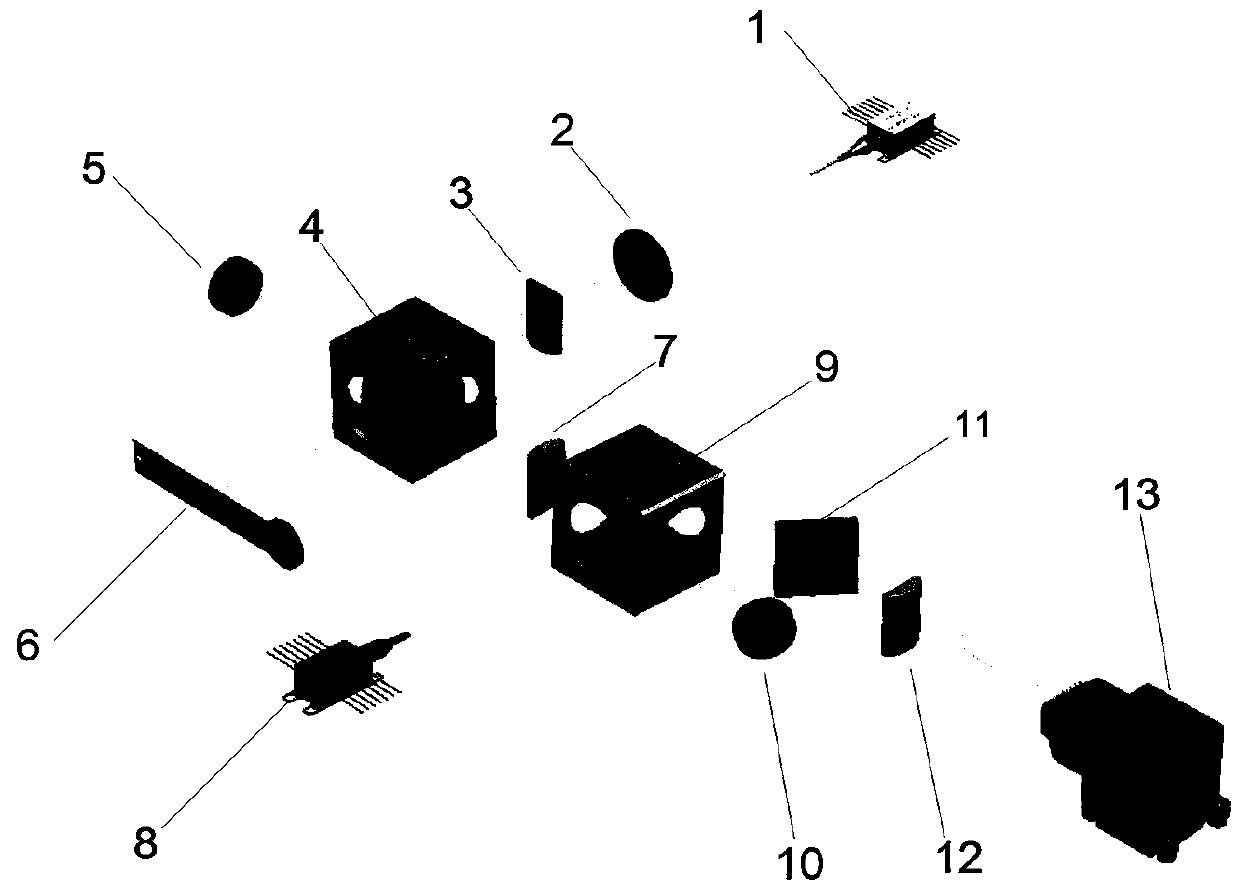
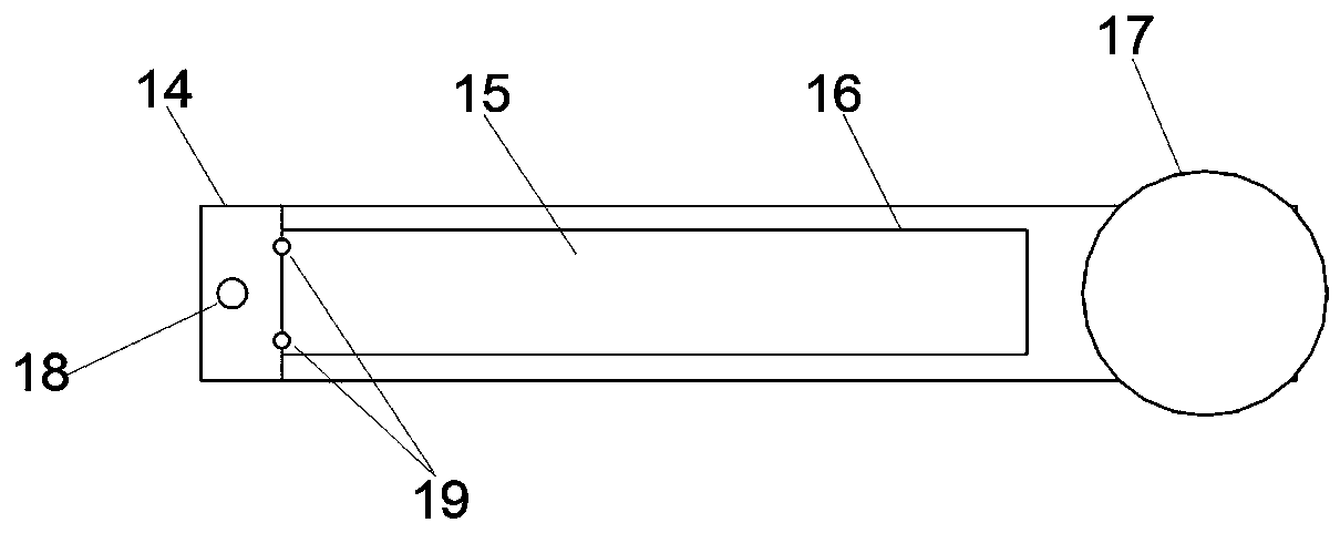
The invention relates to a weighing device and weighing method based on modal frequency of a cantilever beam. The device comprises a tungsten halogen lamp light source module, a Michelson interferometer module, a two-dimensional spectrograph module, a cantilever beam module and a computer. The invention provides a structure modal analysis method that is high in efficiency and accuracy, non-contact, lossless and high in resolution ratio and does not introduce additional weight on the basis of learning and research on vibration detection and modal analysis of a light thin-wall structure piece; by using the method, real-time modal analysis can be performed on the beam structure without knowing the information of a shock excitation input signal, and weighing can be implemented without knowingthe shock excitation input signal.

Description

technical field [0001] The invention relates to the field of optical measurement mass weighing, in particular to a mass weighing device and method based on the modal frequency of a cantilever beam. Background technique [0002] Two-dimensional frequency-domain optical vibration tomography (2D-OCVT) is based on the principle of low-coherent light interference, and uses a high-speed CMOS camera as a detector to obtain the displacement of the vibrating structure by analyzing the interference signal between the reflected light on the surface of the vibrating structure and the system reference light. Information, after spectrum correction, the vibration displacement accuracy of nanometer ultra-high resolution can be obtained. The 2D-OCVT system can realize the line domain vibration test, and the displacement information of multiple points on the line can be obtained at the same time in one acquisition, and the real-time modal analysis of the beam structure can be performed withou...

Claims


Application Information

Patent Timeline
IPC IPC(8): G01G9/00
CPCG01G9/005
Inventor 钟舜聪方波沈耀春钟剑锋
Owner FUZHOU UNIV
Learn More