Scanning galvanometer on laser radar

A technology of scanning galvanometer and laser radar, applied in the field of scanning galvanometer, to achieve the effect of ensuring normal use, easy to move, and ingenious structure

Pending Publication Date: 2018-11-30
WUXI HANGHU TECH
View PDF9 Cites 0 Cited by
  • Summary
  • Abstract
  • Description
  • Claims
  • Application Information

AI Technical Summary

Problems solved by technology

[0003] Purpose of the invention: In order to overcome the deficiencies in the prior art, the present invention provides a scanning vibrating mirror on the laser radar to monitor the distribution of air pollution particles and effectively eliminate the phenomenon of water mist inside the vibrating mirror

Method used


Image

  • Scanning galvanometer on laser radar
  • Scanning galvanometer on laser radar
  • Scanning galvanometer on laser radar

Examples


Embodiment Construction

[0019] The present invention will be further described below in conjunction with the accompanying drawings.

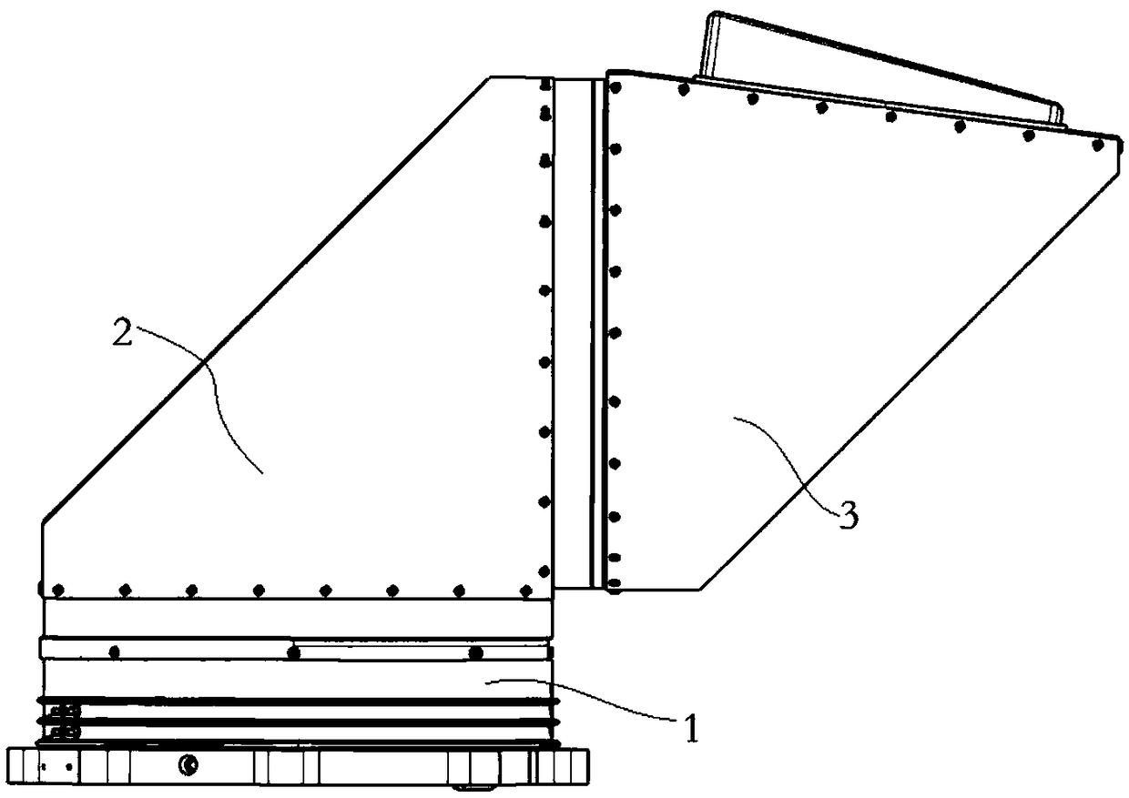
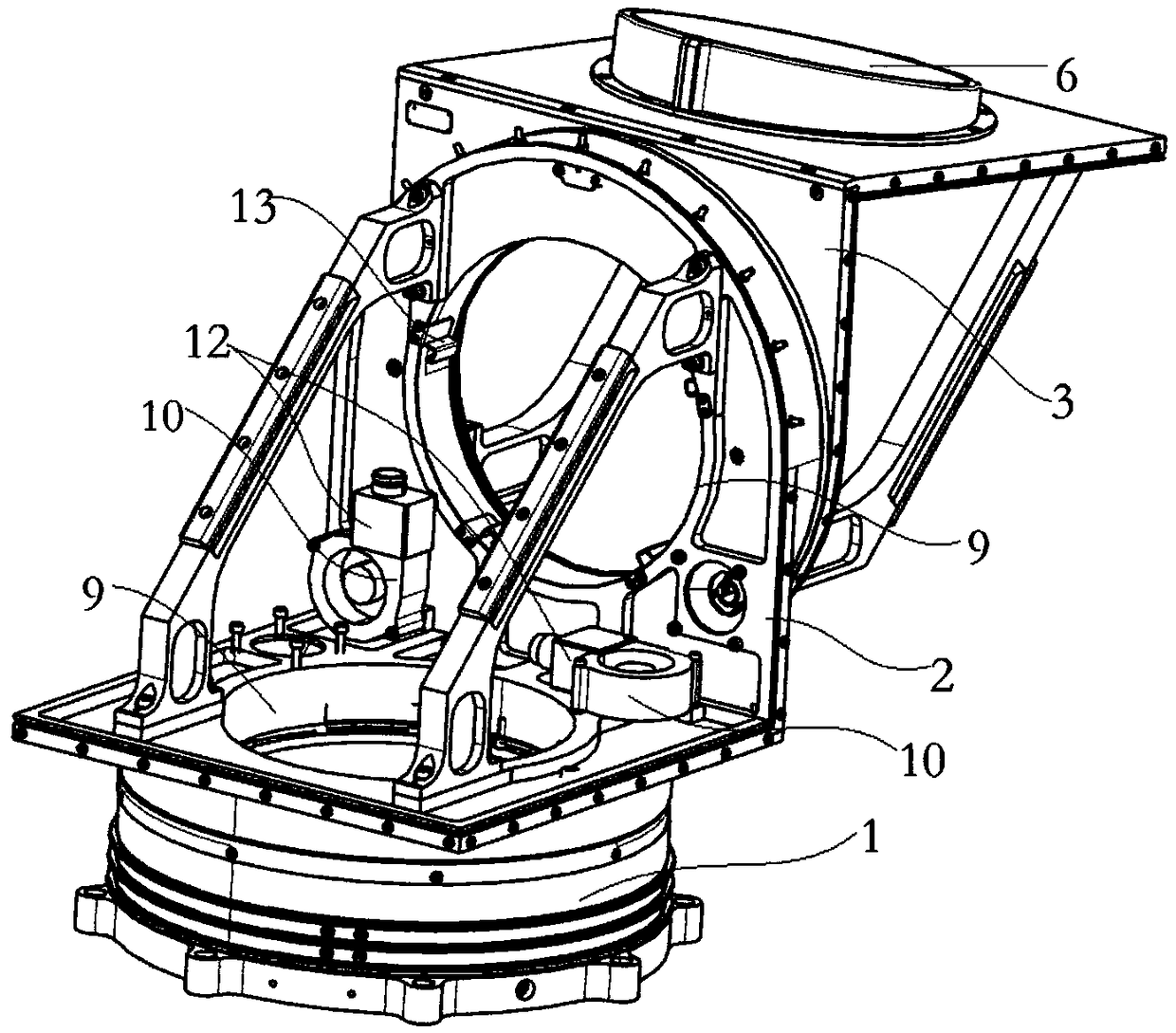
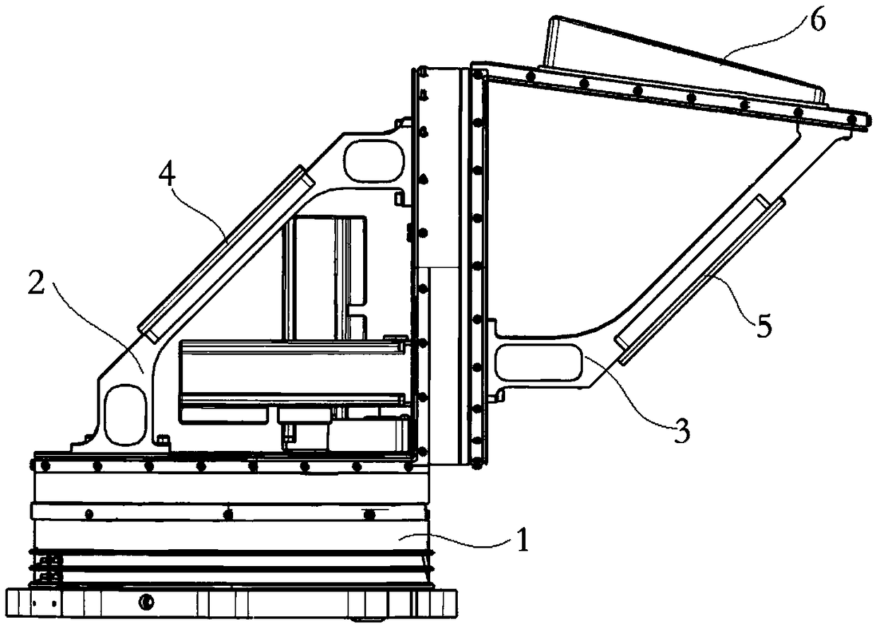
[0020] as attached figure 1 to attach Figure 4 As shown, a scanning galvanometer on a laser radar includes a base 1, a first rotating assembly 2 and a second rotating assembly 3, the first rotating assembly 2 is rotatably arranged on the base 1, and the first The rotation axis of the rotation assembly 2 is perpendicular to the base 1, the second rotation assembly 3 is rotatably arranged on the first rotation assembly 2, and the rotation axis of the second rotation assembly 3 is mutually connected with the rotation axis of the first rotation assembly 2 Set vertically, the first rotating assembly 2 rotates in the horizontal circumferential direction, and the second rotating assembly 3 rotates axially in the vertical direction. The rotation angles of the two rotating assemblies are both 0-360°. The rotating assembly rotates in the horizontal and vertical directions to ...


PUM


Abstract

The invention discloses a scanning galvanometer on a laser radar. The scanning galvanometer comprises a base, a first rotating assembly and a second rotating assembly, wherein the first rotating assembly is rotationally arranged on the base; the rotating axial line of the first rotating assembly is vertical to the base; the second rotating assembly is rotationally arranged on the first rotating assembly; the rotating axial line of the second rotating assembly and the rotating axial line of the first rotating assembly are in mutually vertical arrangement; the first rotating assembly, the secondrotating assembly and the base form a sealed cavity structure; the scanning galvanometer also comprises demisting assemblies; at least one demisting assembly is arranged in the first rotating assembly; the demisting assembly disturbs airflow in the sealed cavity for continuous high-speed flowing, so that the airflow internal circulation is formed. The scanning galvanometer on the laser radar provided by the invention has the advantages that the atmospheric pollution particle distribution is monitored; meanwhile, the phenomenon of water mist inside the galvanometer is effectively eliminated.

Description

technical field [0001] The invention belongs to the field of air pollutant monitoring, in particular to a scanning vibrating mirror on a laser radar. Background technique [0002] Laser radar technology has important application value in the detection of atmospheric parameters and air pollution. As an important ground-based remote sensing device, particle laser radar is a powerful supplement to conventional ground monitoring technology, which can determine the vertical distribution and temporal and spatial changes of aerosols in the atmospheric environment. , which can adapt to the typical pollution characteristics of China. However, existing lidar products have the following shortcomings: most lidar products are used for fixed monitoring, and cannot obtain the spatial distribution information of aerosols; when used in alpine regions, due to the large temperature difference between the inside and outside of the vibrating mirror, water mist will appear inside the lens phenom...

Claims


Application Information

Patent Timeline
Patent Type & Authority Applications(China)
IPC IPC(8): G01N21/39G01N21/01G02B26/10
CPCG02B26/105G01N21/01G01N21/39
Inventor 范罗荣
Owner WUXI HANGHU TECH
Why Eureka
Try Eureka